|
 Click here to order Parts
|
|||
| site search by freefind |
(If you don't see the Google Translate's "Select Language", then your browser is blocking google translate...so enable googleapis.com)
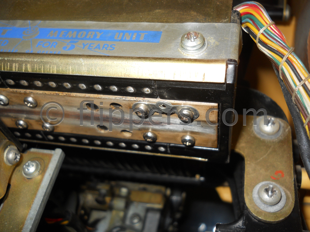
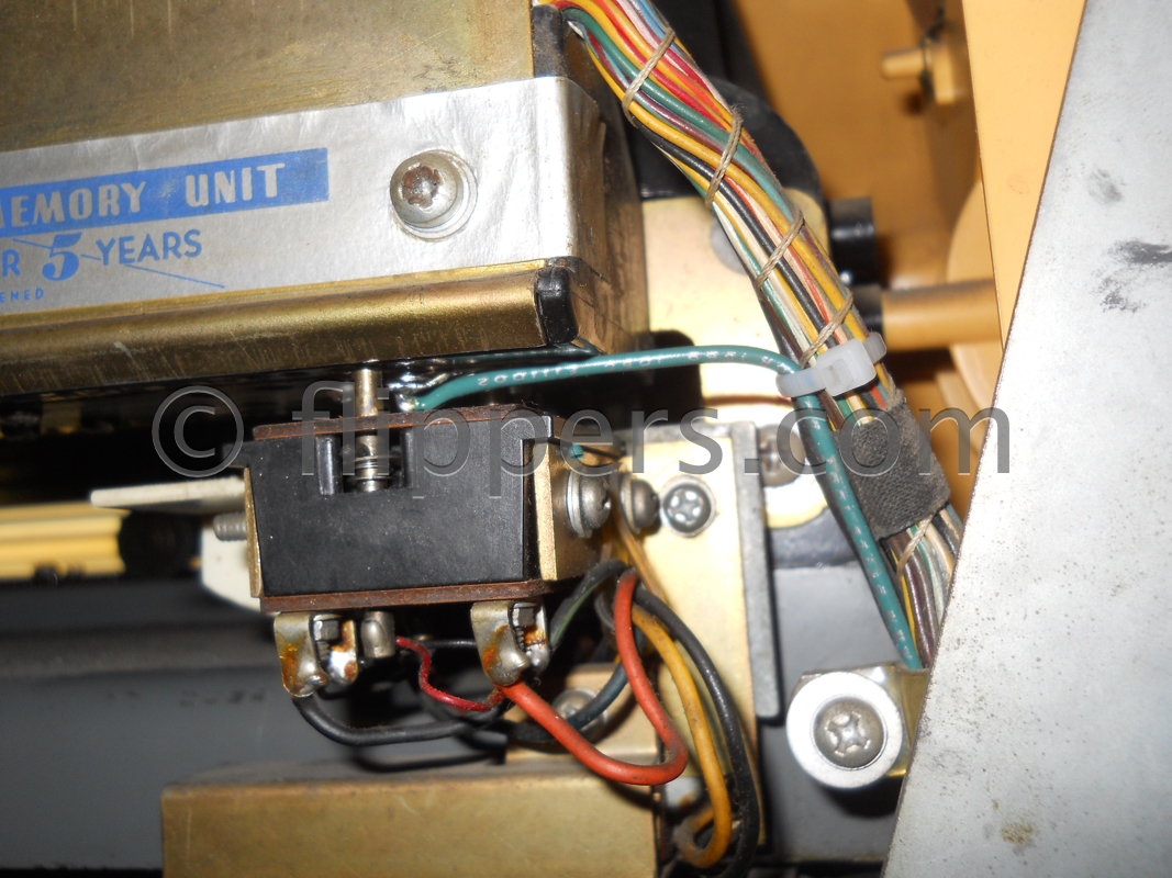
It is not uncommon for Seeburg Tormat systems - particularly the tube based readout style - to have the problem of either extra selections playing when only a few are made or the same record(s) playing over and over again even when you use the battery test to clear the memory (you did get a service manual, didn't you? We sell copies as do others, much better than the download versions!). Sometimes this problem is caused by the Tormat ground plate silver plating wearing off by being either too aggressively cleaned (no abrasives!) or just atmospheric corrosives eating it away. A good ground plate should look like tarnished silver. This tarnish is fine as silver oxide is conductive. When the silver is worn/etched/? away then you will get sparking from the pins to the ground plate and this sparking leads to erratic selections or over selections. The cure is pretty simple, but must be done carefully. 1) Move the carriage to the far end from the cable exit on the Tormat. Then carefully remove one or two screws from the ground plate that are closest to the end, but on the outside edge. These screws are tightened into Speed-Nuts and if you push up on the screws when loose you can pop the Speed-Nut into the inside body of the Tormat which then means you have to take the metal cover off, and you don't want to do that, really. 2) Get your self two (recommend two) small solder tabs that have holes to fit the #4 screw shaft and bend then in a shallow Z so the tab is no higher than around 3mm raised from the ground plate and screw the two tabs in so that they are parallel to the contact heads and the holes line up - so it won't fowl the scanning pins or block. I'd suggest you bring the carriage down to the work end and then away again to make sure there is clearance before going any further. If all is clear then solder a ground wire - 18 to 20 gauge wire - to the tabs and run it along the Tormat wiring harness until it is near the control centre.
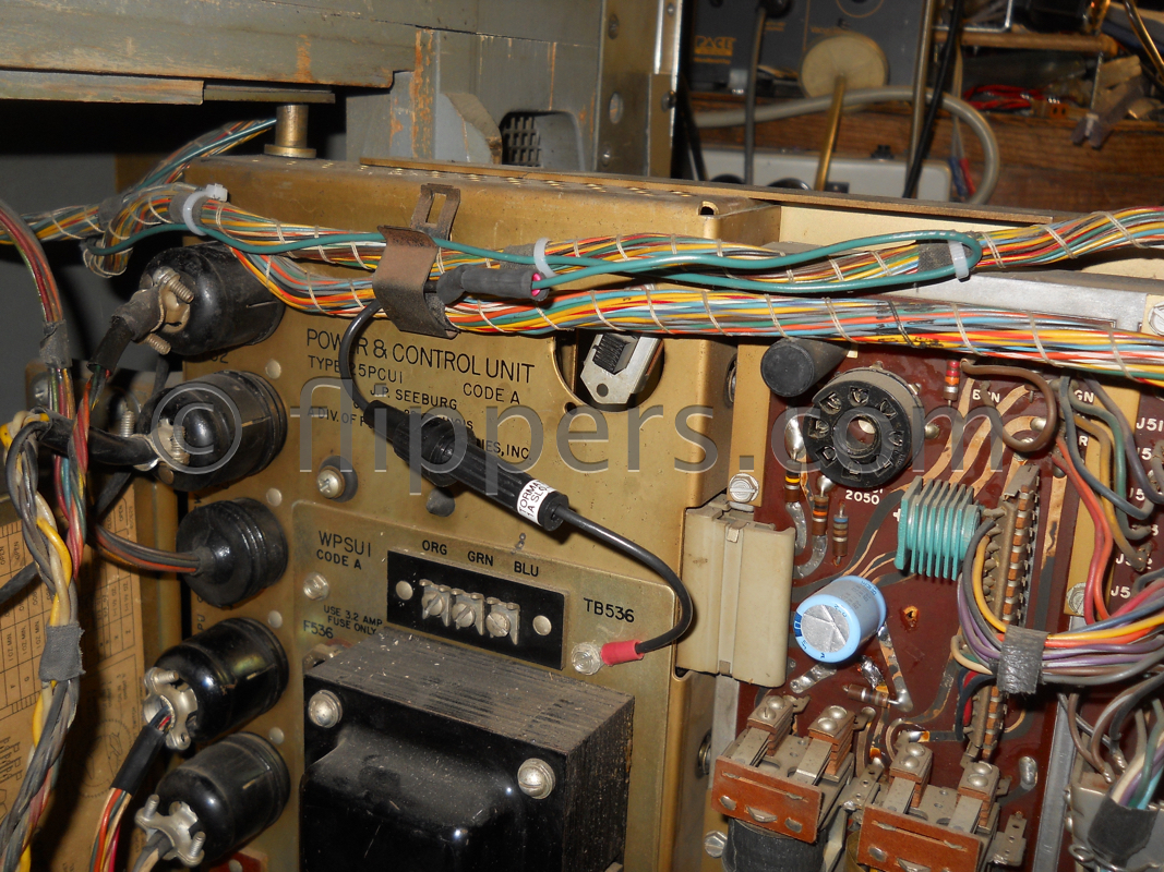
3) Get an inline fuse holder and a 1A Slo-Blo fuse that is rated for 250V. A single pin insulated quick connect is also a good idea. Secure one end of the fuse holder the metal chassis of the control centre or Tormat receiver (if a separate module), connect the other end of the fuse holder to the quick connect and the other quick connect to the ground wire. Secure the wiring with zip ties to the cable, etc, so vibration won't stress the wire and finally cut the pigtail fuse that is on the carriage - this disconnects the wiper pins from the circuit. Don't forget this step!
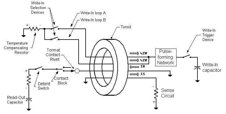
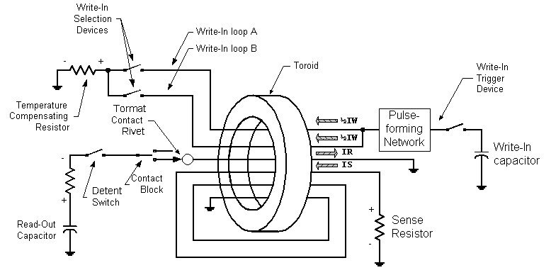
How the Tormat WorksFine, most of the time. But seriously folks, the Tormat was introduced in 1955 model V200 jukebox, and replaced the lever memories used in all Seeburg jukeboxes up until then. Between then and its last use in the STD4 (1974), it went through a number of refinements in the design of the Write-In, Read-Out and Sense circuits. But the basic operation has remained the same. So what the Tormat does is to provide a memory to keep track of records which have been selected but not yet played. First, some terms need to be defined. 'Write-In' refers to the process of entering a selection into the memory for playing. 'Read-Out' means that the memory is interrogated to determine if a selection was previously written-in. 'Cancel' means to eliminate a previously written-in selection. The old lever memory had a mechanical lever for each record side. Each lever had two positions, selected and unselected. Levers were organized into two banks, one for each record side. Each lever had a magnet, which was used to move it from the unselected to the selected position. Every twenty levers had another magnet, called the group magnet, associated with them. This magnet was involved in the selection Write-In process, to complete the Write-In Circuit. Any lever in the selected position also completed a circuit which applied power to the mechanism motor, causing it to scan to look for selected levers. This function is called 'play control'. There were a pair of switches mounted to the mechanism carriage on an assembly known as the 'contact block', one of which would close whenever it struck a lever which was in the selected position. Only one contact block switch was active at a time, as determined by direction of mechanism travel. Whenever one of the switches sensed a lever in the selected position, the mechanism tripped, and the record was transferred into the play position and played. Thus Read-Out occurred as the mechanism scanned and detected a selected lever. As the record was transferred to the turntable, a solenoid energized which pushed the lever back into the unselected position, which Cancelled the selection. The Tormat Memory Unit replaced all these levers, magnets, and solenoids with a group of solid state toroids. Toroids are small (approx. 3/16 inch outside diameter) donut-shaped rings made of ferrite (magnetic) material. Like the lever memory, there is one toroid for each record side. Each toroid has several wires threaded through the hole in its center. A current beyond a certain critical value passing through a wire will cause a magnetic field to be induced in the toroid. The field induced will be in one of two orientations, determined by the direction of current flow through the wire. Any current less than this critical value (about 1½ Amps) has no effect on the field. So, the toroid can be said to have 'hysteresis', meaning that it is insensitive to currents less than the critical value. Once that critical value has been exceeded, the field will rapidly change to the other state and will stay there until a current exceeding the critical value is passed through it in the opposite direction. Note that repeating the current application, or increasing the amount of current applied beyond the critical value has no effect: once selected or de-selected, it cannot be 'more' selected or deselected. One magnetic field orientation is defined as the selected state, the other is the unselected state. Since the toroid will remain in one state or the other when the current is removed, the memory is referred to as 'non-volatile'. Indeed, the only time current flows in the toroid wiring is when it is written-in or Read-Out. Since there are no moving parts in the Tormat and therefore almost nothing to go wrong, Seeburg graciously warranted it for a period of five years. The fact that the toroid is insensitive to currents below the critical value is the idea behind the selection system. If two simultaneous currents, each slightly greater than half the critical value, are passed through separate wires each threaded through several toroids, only the single toroid which has both wires passing through it will be flipped to the selected state. Each of the wires then forms a loop, through several toroids, arranged so that each toroid has two Write-In loops threaded through it. One loop is for the letter group, the other for the number group, or one will be the tens digit loop while the other is the units digit loop, etc., depending upon selection system. Each toroid is housed in a small cup molded into a plastic housing screwed to the metal base plate of the Tormat. This plastic housing contains the gold-plated contact rivets at the bottom of the Tormat. Between the metal plate and the plastic housing is a metal contact plate with formed terminals. Due to its' connection to the base plate, these terminals are connected to ground, and form the ground return of the Read-Out loop. The toroids are held in place by a phenolic board, screwed to the top of the plastic housing. This board has several terminals staked to it. The toroids are further secured in place by the wiring threaded through them. Each toroid is associated with a record side, and is mounted physically close to the contact rivet for that record side. This location is what establishes the 'address' of the toroid (the selection number), which varies according to the selection system used. For example, selections A1 and B1 are opposite sides of the same record for all of the non-digital machines. The black and grey box machines (160 selection boxes LS3 through STD4) use 100/200 for the left side selection. The 100 selection machines used A1/A2 for opposite sides of the same record, while the 10077D and 10078D used 00/01. After assembly into the molded plastic holders, it is time to wire the various loops. Let's talk about Write-In first. How the toroids are wired for Write-In varies a lot depending on the selection system, but basically there are two loops of wire threaded through each toroid which are used for Write-In. Each toroid is thus wired in an N x M matrix for Write-In. The 100 selection machines used a 10 x 10 matrix. The 160 selection non-digital machines used a 20 x 8 while the digital 160 machines used a 2 x 8 x 10 matrix. The 200 selection machines used a 20 x 10 matrix. It is this matrix of wires which gives the Tormat its name, short for 'TORoid MATrix'. It is vital to note that all of these Write-In loops pass through the toroids in the same direction, so that their half currents will add. Each toroid has another loop of wire passing through it, in the OPPOSITE direction of that used for the Write-In loops. This is the Read-Out loop, and is connected from the terminal on the grounded metal plate, looped through the toroid, and connected to the associated contact rivet. For most machines there are as many Read-Out loops as there are selections, one for each record side, toroid, and contact rivet. Exceptions to this are the 12 inch home LP machines and those 7 inch record machines which played both sides of the record (if selected) in succession. These machines search for selections while scanning in one direction only, and both toroids for a record are read out simultaneously. Each record side has a trip relay, which is used to implement the 'play one side followed by the other' scheme. Examples of this type machine are the LPC1, and LPC480. Due to the way it is wired, the Read-Out loop will conduct current in the opposite direction to that of Write-In. This current is used to interrogate the toroid, to determine if it was previously flipped to the selected state. The act of reading-out a toroid serves to Cancel the selection, if the toroid was indeed selected. This feature comes for free. The earlier machines used a sliding contact on the contact block to complete the ground connection for the Read-Out loop to the Tormat base plate. This contact slides along the metal base of the Tormat and is the cause of some of the intermittent selection problems encountered with these machines. Over time, the bar gets dirty or rusty (even though it was plated), making poor contact which results in sparking between the contact and the plate, making matters worse. The solution is to clean the plate and reshape the contact so that it forms a dome. In severe cases of base plate corrosion, since the back side of the base plate should be clean, the best thing to do is to gently remove the base plate from the Tormat, turn it over, locate and drill new mounting holes (since they will now be in the wrong position), and reassemble it. It is best to leave the cover on the Tormat to prevent breakage of the internal connections. Finally, all toroids have another loop of wire threaded through them, the Sense loop. Machines prior to the PFEA1 (those which used tubes in the trip circuitry) have one loop of wire in the Sense loop, while the solid state machines use three loops. The Sense loop threads through every toroid in the same direction as the Write-In loops. The function of this loop is to sense that a toroid was previously written-in when Read-Out of that toroid occurs. If the toroid was previously flipped to the selected state, it will flip back to the unselected state when the Read-Out current pulse is applied. While flipping back to the unselected state, a pulse will be induced in the sense loop of the correct polarity to fire the trip thyratron (tube machines) or SCS (solid state) in the Selection Receiver or Control Center. The later jukeboxes used three loops of wire to simplify the sense circuitry, eliminating the pulse transformer and pulse stretching circuitry of the earlier machines, making it easier to discriminate against noise pulses. It should be noted that Write-In will also induce a current into the sense loop. The polarity of this current is opposite that of Read-Out and is ignored by the trip circuit. The drawing below shows the wiring of a Tormat used in a tube-type jukebox:
Write-In loops A and B form the matrix discussed above. Each is activated by closing the appropriate Write-In Selection Device, which in this case will be a selector button. Once the second selector button has been pushed, the Write-In Trigger Device will close to discharge the Write-In capacitor through the Pulse-forming Network, two loops, the selector switches, and the Temperature Compensating Resistor. This resistor is used to keep the Write-In current relatively constant with changes in ambient temperature, and is physically located within the Tormat. The Pulse-forming Network is used to control the wave shape of the Write-In pulse. The Write-In Trigger Device is the special rotary switch in the Pricing Unit which closes as credit is subtracted for the selection. This switch is basically a printed circuit foil segment with sliding contacts, used to minimize the switch 'bounce' that normally occurs with other types of switches. For Write-In, each half-current flow is shown by the ½ IW dashed arrow to the right of the toroid. For Read-Out, the Read-Out Capacitor is discharged each time the Detent Switch closes. The capacitor discharges through a current liming resistor, the Detent Switch, a pulse-forming inductor (not shown), the contact block, the Tormat Contact Rivet, and finally through the toroid to ground. Read-Out current is the full critical value, and flows in the opposite direction to Write-In current, as shown by the IR dashed arrow. If the toroid was written-in, Sense current IS will be induced into the Sense Loop, with the current flow inducing a voltage across the Sense Circuit with the polarity shown. The first couple of Tormat jukeboxes used an elaborate thyratron tube-based Read-Out circuit, but all later machines used the simpler circuit shown here. The next drawing shows the wiring of a Tormat used in a solid-state Jukebox:
Note that the current polarities here are reversed, due to the switched power supply polarity. The Write-In Selection devices are still the selector buttons unless the jukebox used the Black & Grey or Red boxes, in which case the switches were replaced by SCSs. The Write-In Trigger Device will still be the printed circuit switch discussed above, except for those jukeboxes using the Black & Grey boxes, which used an SCS, or the Red box, which used a relay. Note that the Write-In and Read-Out circuits are otherwise identical, except for the direction of current flow through the toroid. The other major difference here is the three turns of wire in the Sense Loop, used to trigger the Sense SCS in these jukeboxes. The trouble shooting section talks about how to flip all toroids to the selected state by using a battery. The reversal of power supply polarity between the tube jukeboxes and the newer solid state machines is the reason why the battery connections must be reversed when doing this on the other type machine. Tormats usually require minimal maintenance. The Mechanism Adjustments Manual details several adjustments which must be performed in order to insure proper alignment between the contact block, Tormat, and record magazine. In addition, several adjustments must be performed to insure the proper detent switch timing, which in turn affects the Read-Out and sense loop timings. The Tormat contact rivets must be kept clean and lightly lubricated, as do the Tormat cable contacts going to the selection system and the sense loop cable going to the Selection Receiver or Control Center. The troubleshooting section details a procedure to use for determining if you have a Write-In, Read-Out, or Sensing problem. If all contacts are kept clean and the proper adjustments have been made, the only possible Tormat problem could be a broken wire or frayed insulation where the cable exits the Tormat. If any of the wires short to ground, this could result in selection problems. |
(jrr-at-flippers-dot-com for those who do not have their browser set to open their email client) |