|
 Click here to order Parts
|
|||
| site search by freefind |
(If you don't see the Google Translate's "Select Language", then your browser is blocking google translate...so enable googleapis.com)
AMI/Rowe Jukebox technical tips
|
 |
 |
 |
 |
 |
 |
 |
 |
 |
 |
 |
 |
 |
 |
 |
 |
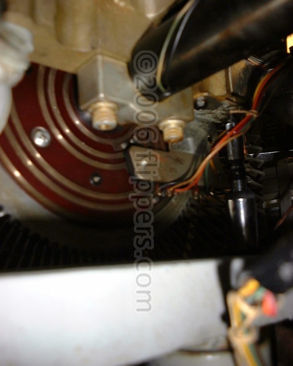
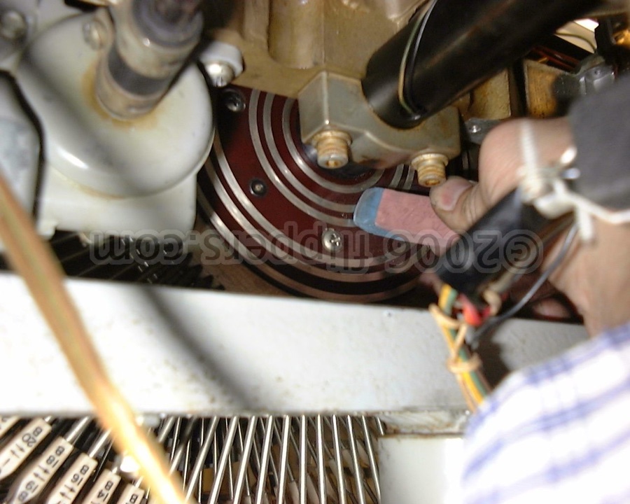
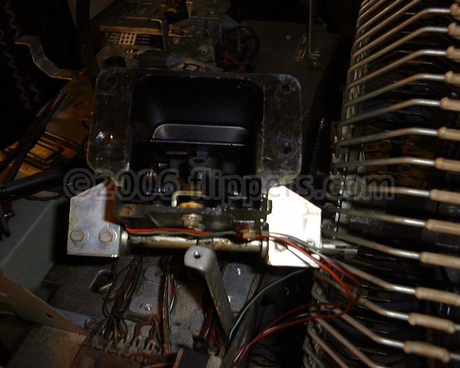
The wiper ring blades that connect the ferris wheel drum electricals to the machine are dirty.
Here are the wiper blades and their rings, you can see these from under the front of the mechanism towards the center....clean the copper rings with an ink eraser and check that the wipers have some pressure on the rings once remounted.
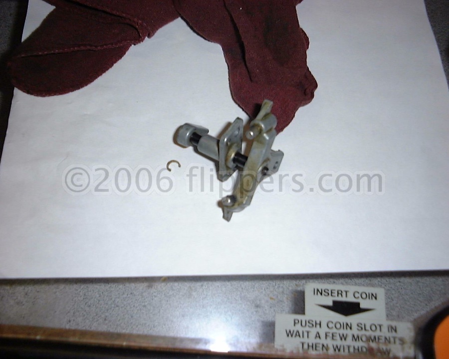
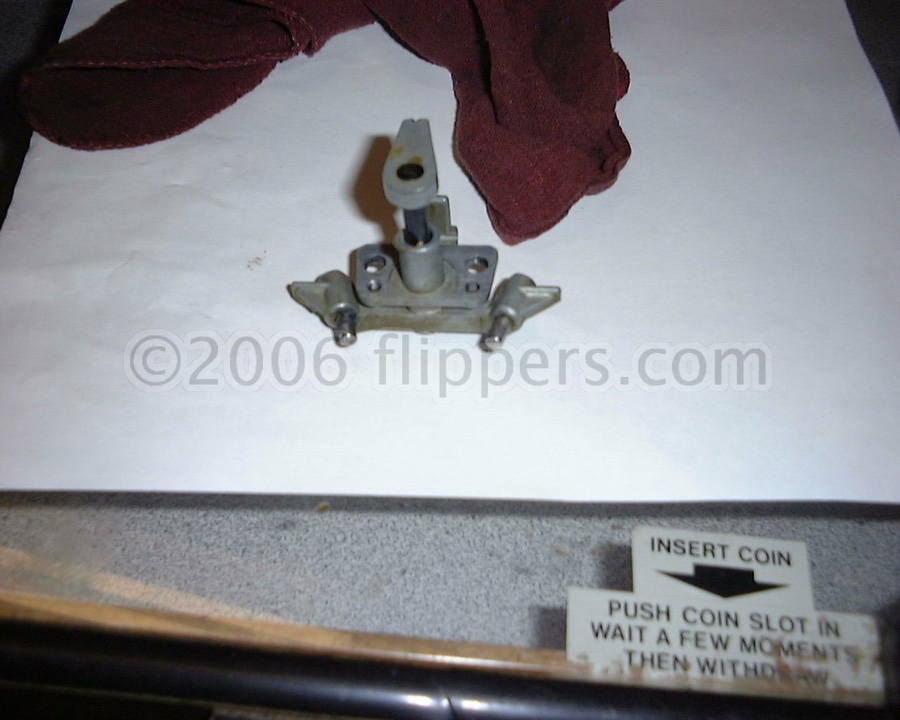
The microswitches that control the selection and cancel of the pins are faulty.
Check all the machines microswitches with an ohm-meter. The readings should be steady once the switch has 'clicked' (either way). If the reading bounces around while pushing on the microswitch actuator after hearing the click then I suggest you change the micro-switch. Best if you have an analog meter, but a digital one works fine as long as it is not one of those auto-ranging ones.
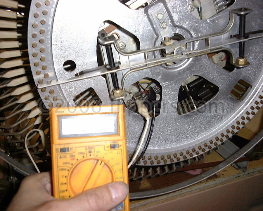
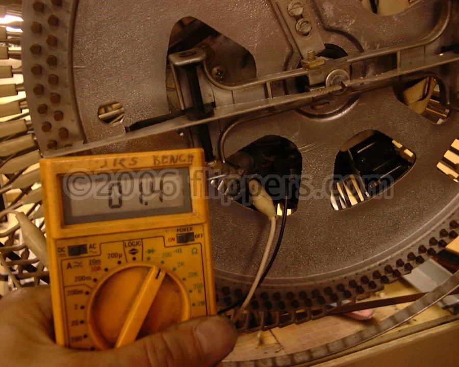
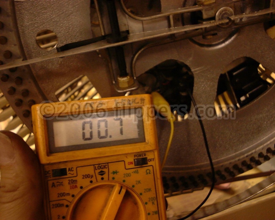
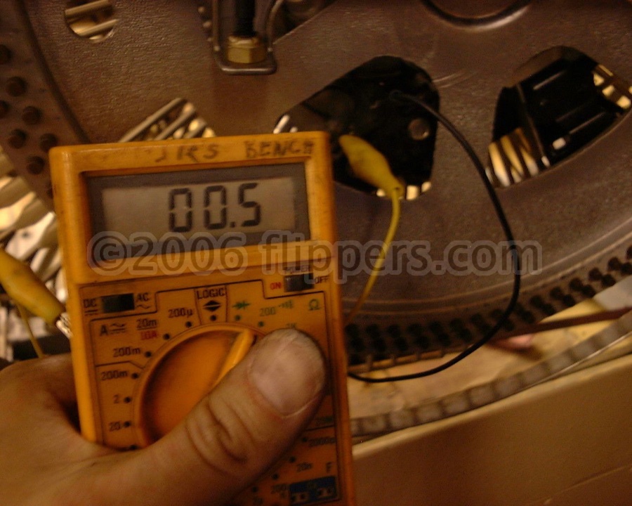
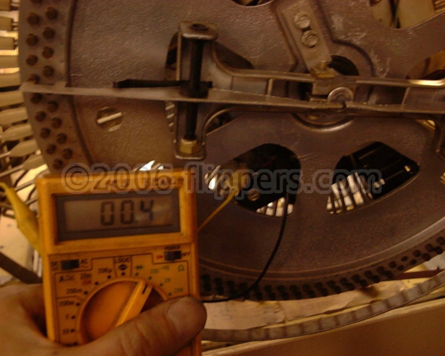
For the folks new to multimeters about the safest use you can put them to for servicing jukeboxes is the Resistance tests. These are all best done with the jukebox unplugged. You simply need to gain experience in reading resistance across contacts of switches, microswitches, and blade switches/wipers to learn if they are working correctly or not.
It is very important to have a good connection between the probes of your meter and the item you are testing. I recommend using a healthy pair of alligator jumper wires that with one end on each of the probe tips, and the other to grasp the lug of the switch in question and read the resistance when the switch is both open and closed.
A point to consider when testing switches is if the switch is still soldered into the circuit when the switch is open it still may indicate a short as an switch somewhere else in parallel with it may also be closed (cancel circuits for example)
I am using the convention that the letter "R" is used to indicate the period place holder when measuring resistance.
With an ohm-meter (resistance) set to the lowest setting (200R or less) a good switch will show about 0.2 ohms (0R2) resistance - remember to check the lead resistance first and to mentally subtract that from any reading - probes shorted should show about 0R2 to 0R4 (ohms).
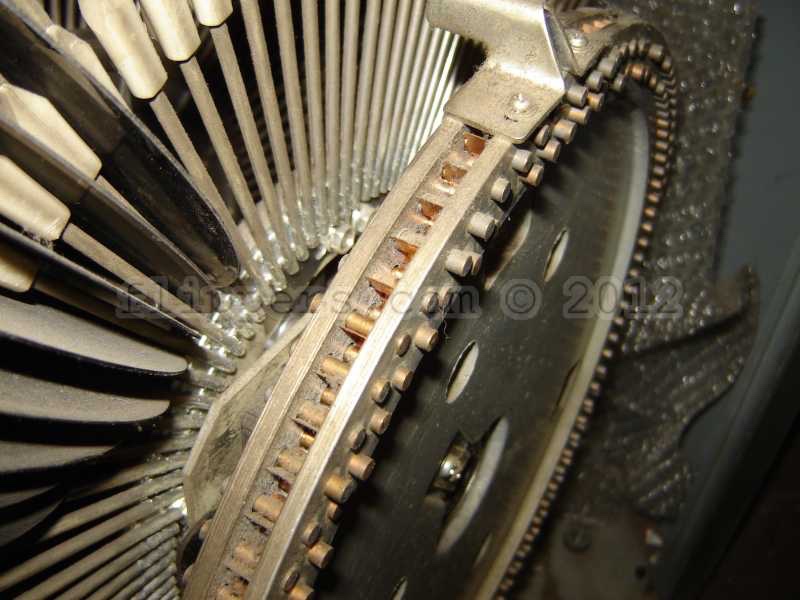
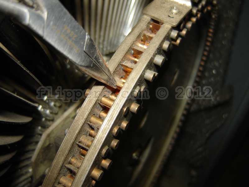
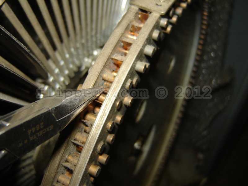
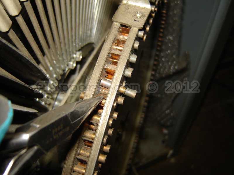
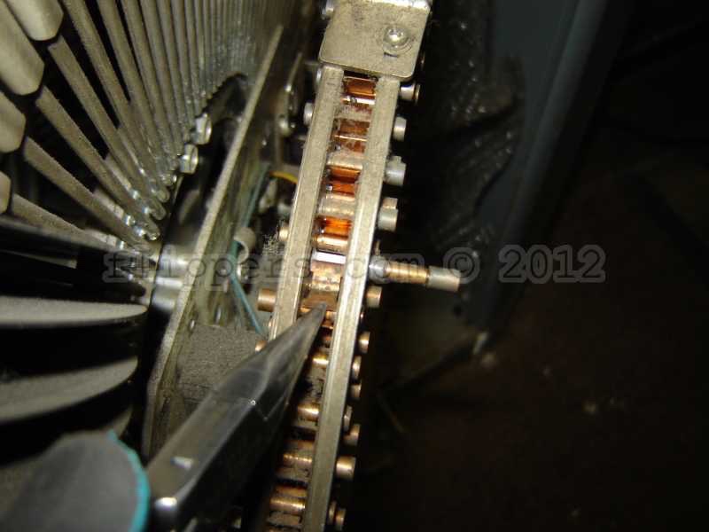
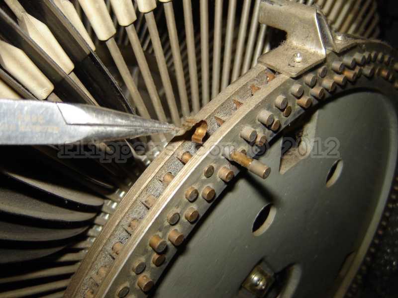
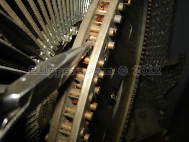
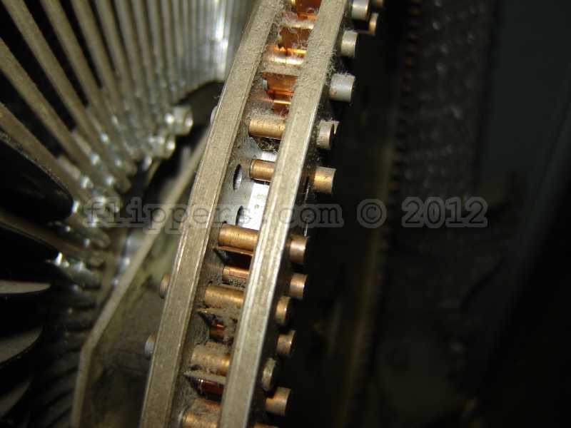
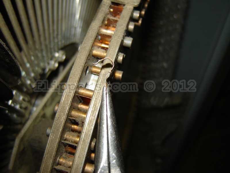
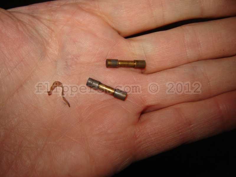
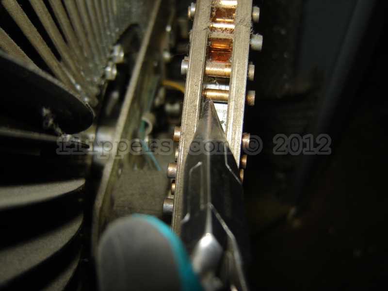
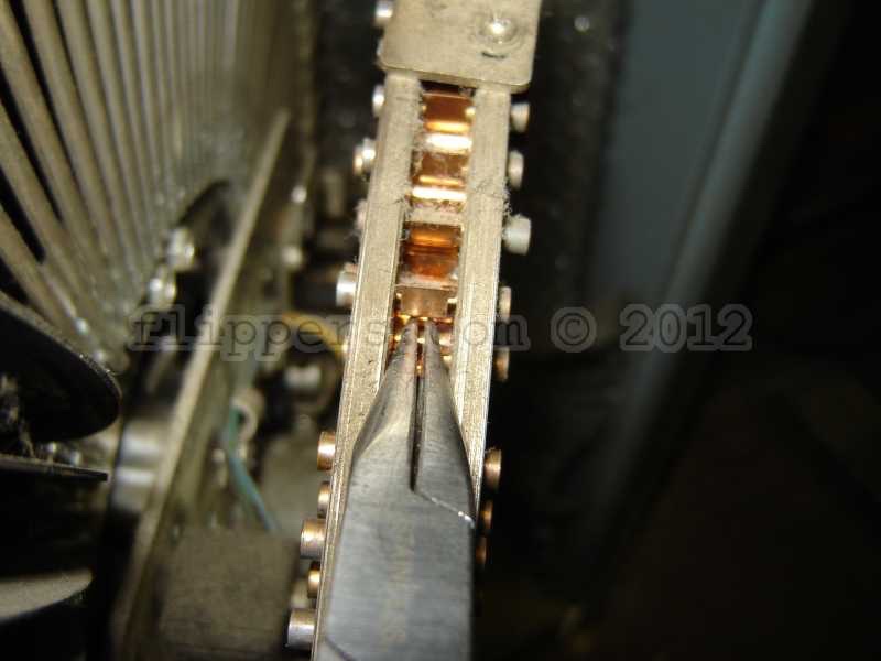
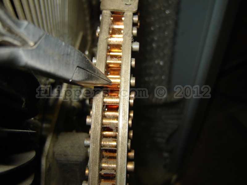
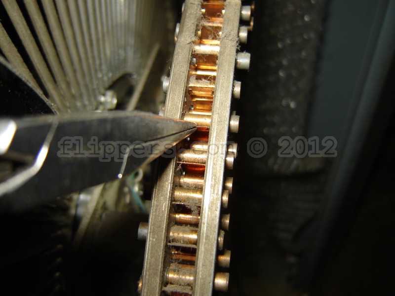
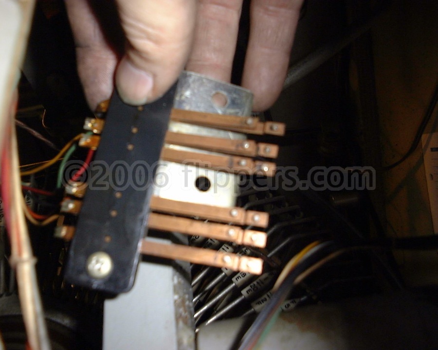
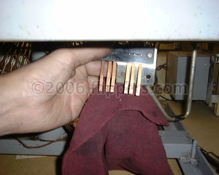
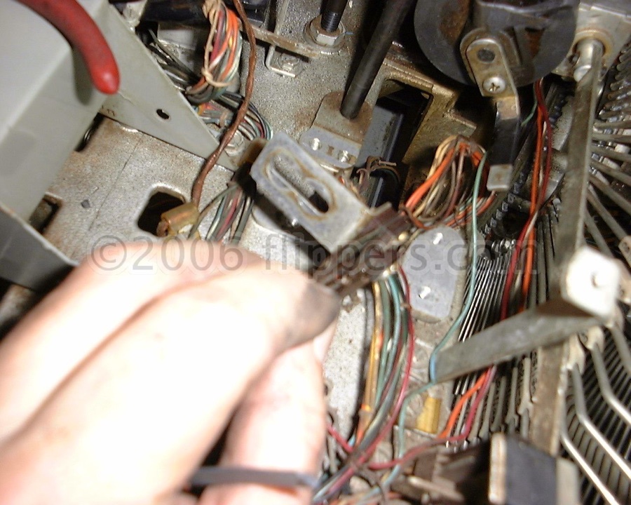
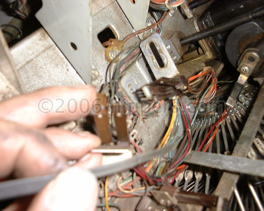
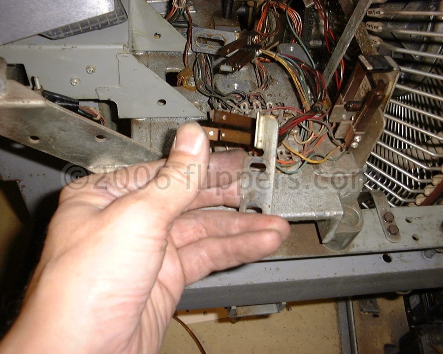
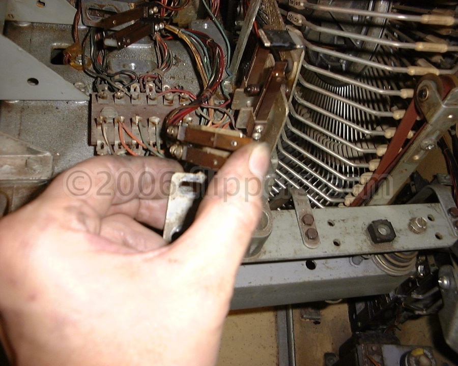
The cam switches (blade style for the A through K, microswitch after) are faulty - common symptoms are 8/10A Slo-Blo (1A Slo-Blo is OK, nothing higher please!) fuse pops and the gripper motor is jammed. Clean the cam switches carefully, do not lubricate with ANYTHING. Polish the contacts with a burnishing tool - you want the contact faces to reflect a smooth, mirror-like finish...
Symptoms/Problems:
SELENIUM RECTIFIER REPLACEMENT:
Slow gripper motor. and/or rotation of ferris wheel -check for 24VDC at the motor when the motor is running, it should be no less than 24V. If it is then check the bridge rectifier in the transformer/fuse box, if it is a Selenium Rectifier (a series of metal plates on a central shaft with three or four lugs that wires are soldered to) then you probably need to replacc it with a modern Silicon Bridge rectifier (10A/100PIV minimum) taking care to match the negative and positive and AC terminals to the old part. I'll post some pictures the next time we do this conversion... Some folks are still making these.
(needs editing pictures to follow - Oct 17, 2021) You can replace the original Selenium Rectifier with a more modern Silicon bridge rectifier, you just have to first identify the output fuse on the original device and that will be replicated on a new fuse and holder that you will add to one of the AC input terminals to the new bridge.
How to identify the terminals on the original selenium rectifier:
There are usually five terminals coming radially out of the centre of older selenium rectifiers. The centre most terminal is the positive terminal. The next terminal on each side of the positive terminal is one of the two AC terminals. The outermost terminals are normally shorted together with a heavy solid wire and are the negative terminals.
You can replace this with any bridge rectifier rated at 25A or more, and a minimum of 100VAC (for spikes),
You absolutely MUST add a fuse on the one or both AC terminals (both if the secondary windings that feed the bridge is Centre-Tapped) and the value of the fuse can't be more than the total of the original factory recommended fuses for the DC output(s). It can be Slo-Blow. It is there to protect the transformer in case the silicon rectifier shorts out...(needs editing...)
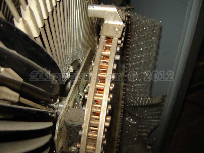
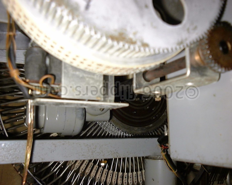
These pictures show various test points and assemblies used in the Ferris wheel style Rowe/AMI jukeboxes.
This is the side A / B rocker showing the spring assembly if you've taken it apart and can't recall how it goes back together...
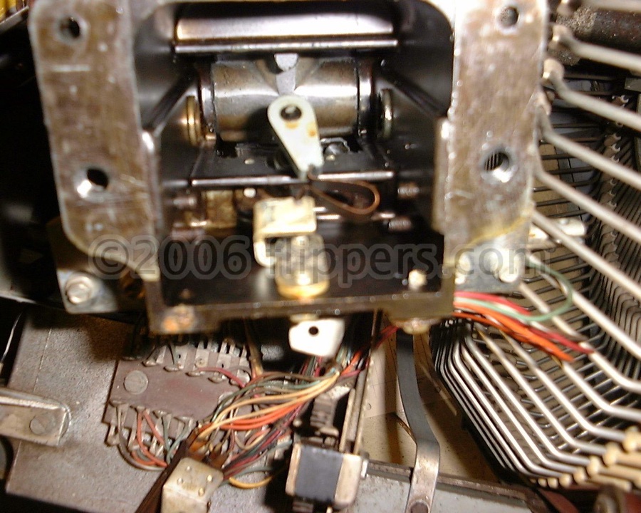
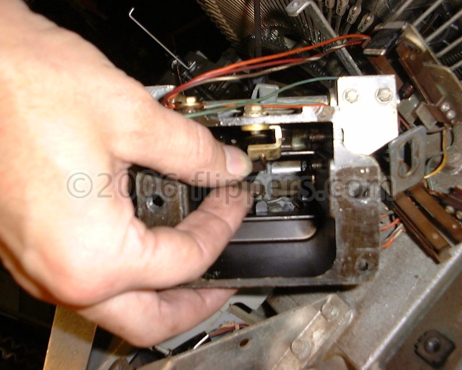
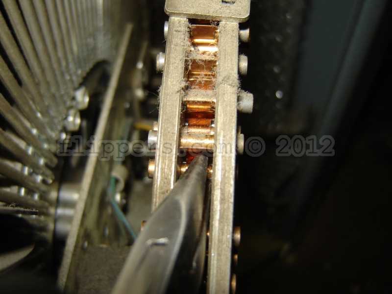
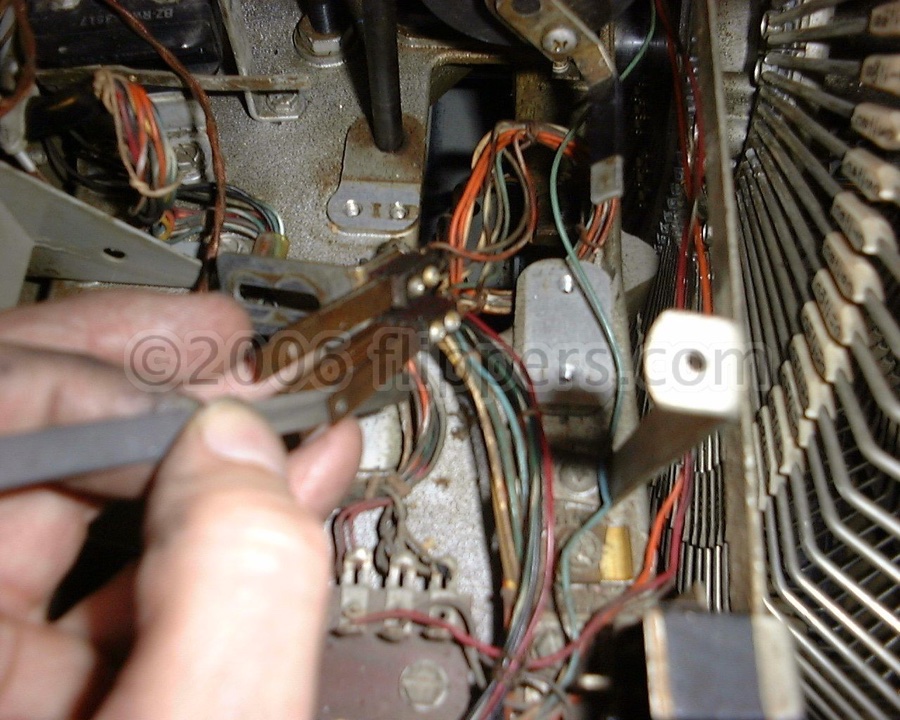
Here are the !@#$! cam switch blades...I dismount them for ease of cleaning... checking alignment carefully when putting back!
PDFs now available for the AMI Model D: R-200 Mechanism Service Manual (D-40) This needs to be printed on Ledger size paper - 11" X 17" and then folded. 3.66mb in size...
Full copies of most of the early AMI manuals are available from us for $25 - $35, email the model you need.
1980s & 90s ROWE/AMI jukebox tips...
Many of the record playing mechansims may have trouble lifting the tone arm enough so that the sytlus needle will clear the gripped bow, due to wear on the lift portion of the tonearm CAM. The solution is simple, simply bend the lift lever slightly either inwards or outwards from the worn indent by about 2cm (3/4") and then adjust the tone arm lift for proper clearance. A dab of grease where the lift link rides up the cam would be in order as well.
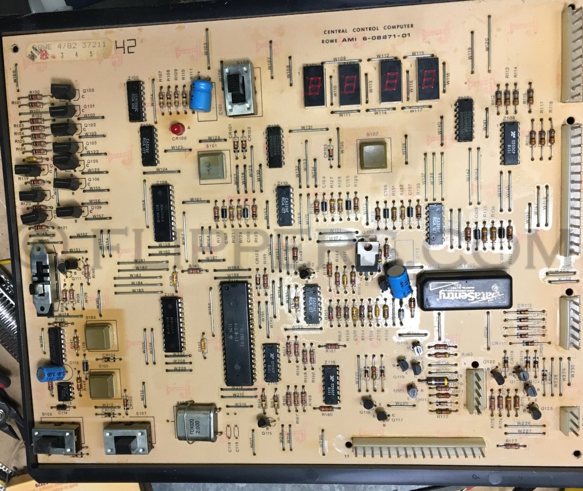
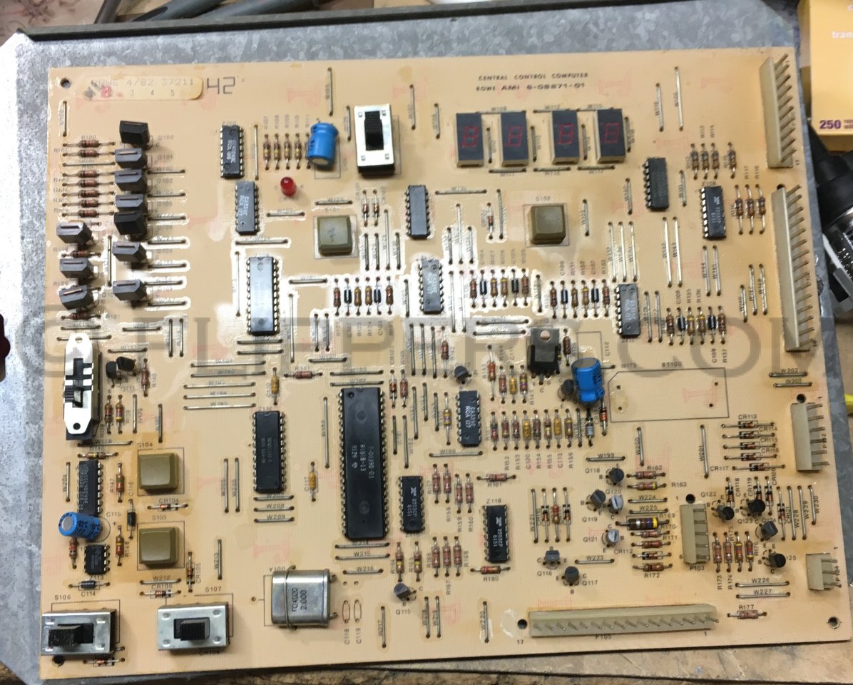
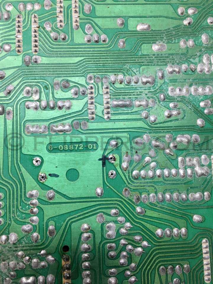
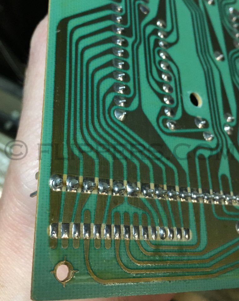
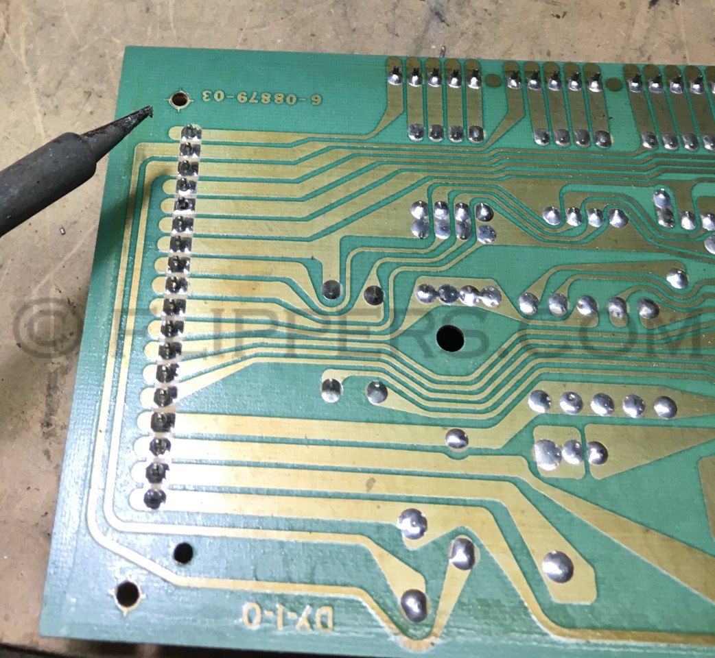
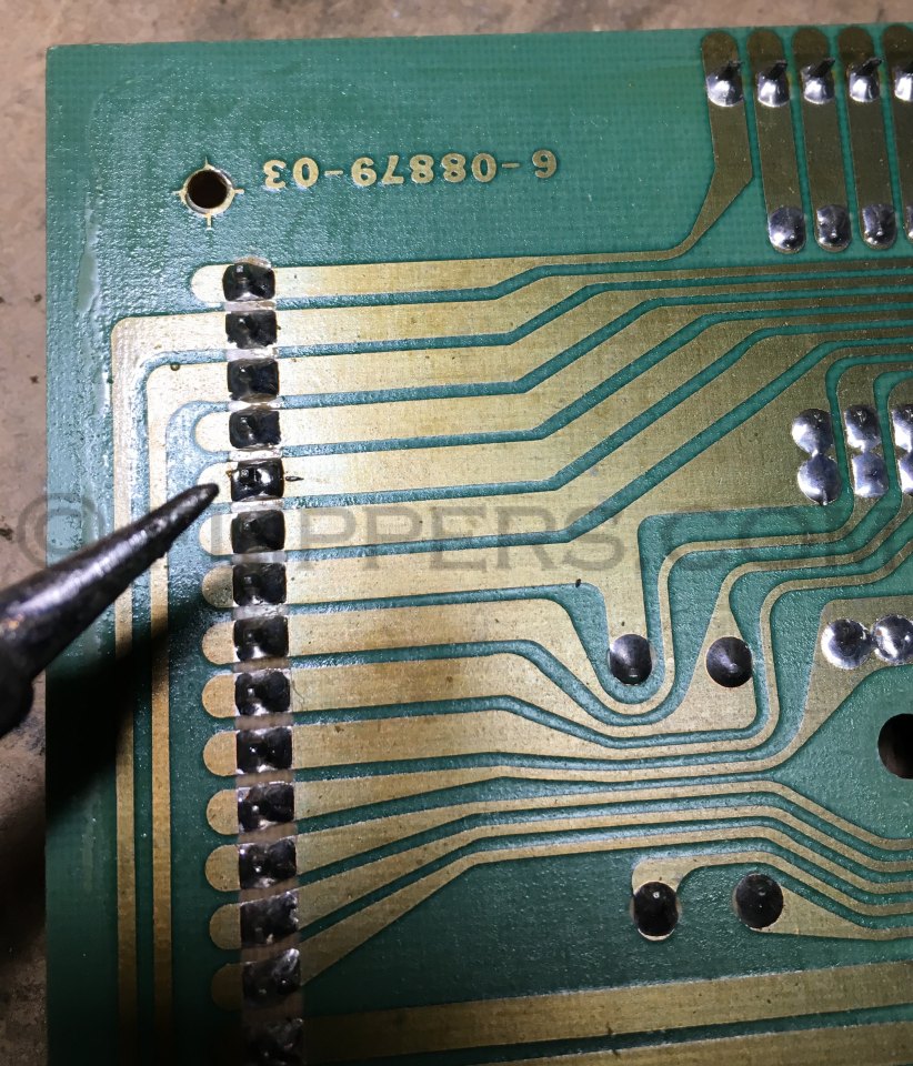
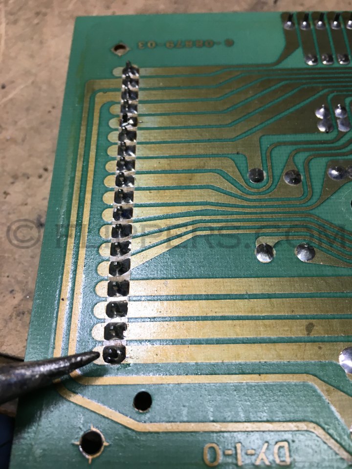
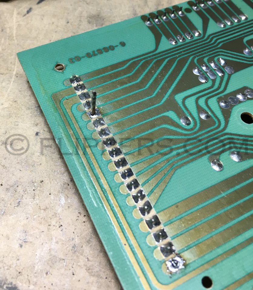
R-86 and earlier models in the R-XX series, these all used single sided Printed Circuit Boards (PCBs) and this creates a problem with the Molex pin connectors used to connect any of these boards to the jukebox wiring harness - the solder connections can fracture at the base of the pin. So, what our shop does before doing any other repairs is we remove the Central Credit Computer, the Coin Programming PCB, and the Mechanism Control PCB and we touch up all the pin connections where they are soldered to the logic boards. In many cases you will see cratering around the pin in the solder connection
Central Computer PCB pins - examples of cracked solder connections and repairs:, and battery location:
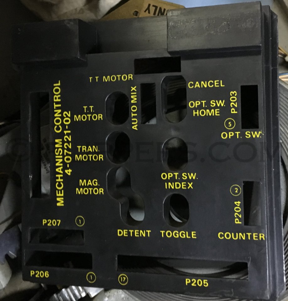
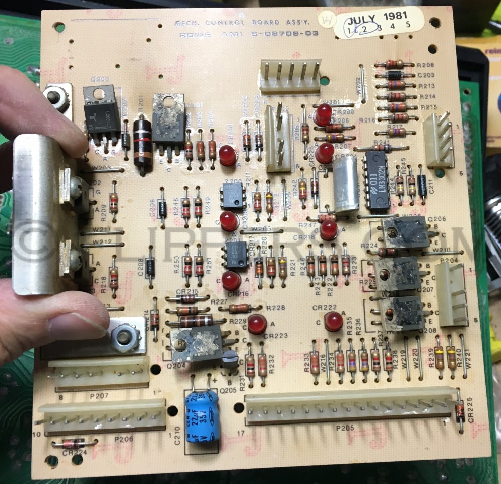
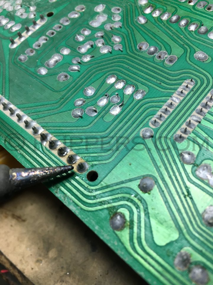
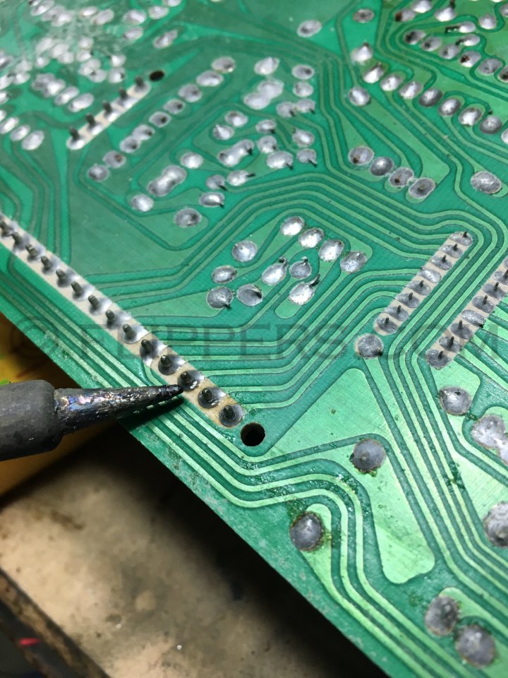
Mech Control PCB:
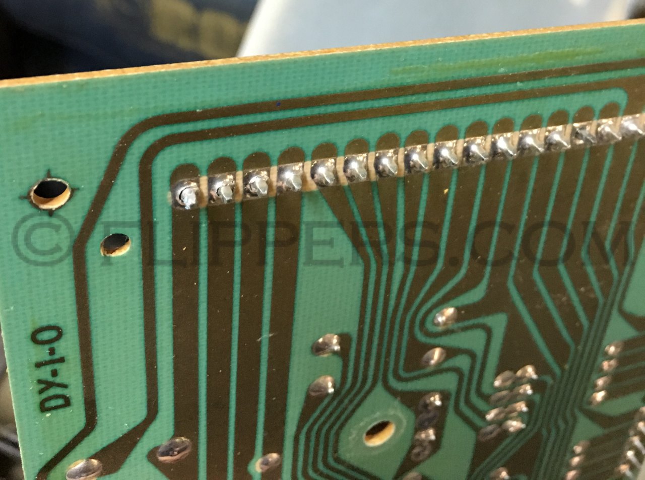
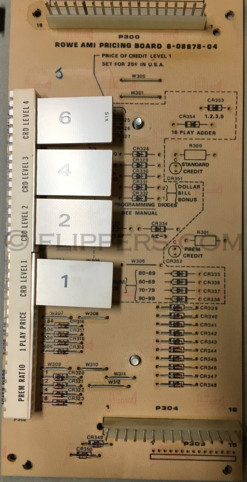
Pricing Control PCB - examples of cracked solder connections and repairs:
Cross Reference chart I found back in 2011 and forgot to add to this page!:
| ROWE - NEW # | ROWE - OLD # | POLARITY | TYPE | GENERIC | ALT'S - check pinouts! | Used in |
| 700-300-01 | S300A | NPN | SILICON TRANSISTOR | MPS 6513 | X32B4680; SPS6978; | |
| 700-300-02 | S300B | NPN | SILICON TRANSISTOR | MPS 6514 | BC 548; X32B4682; SPS6979; | |
| 700-300-03 | S300C | NPN | SILICON TRANSISTOR | 2N5210 | GE X32B4686; SPS6980; ? MPS 6513 ?? | |
| 700-300-05 | S300E | NPN | SILICON TRANSISTOR | 2N5219 | 2N3391(check pinout); TZ1205; SPS1481; 2N5209; X32B4683; | |
| 700-300-08 | S300H | NPN | SILICON TRANSISTOR | MPS-A06 | TI: SKA 3368 | CD juke power supply Q503 |
| 700-301-04 | S301D | PNP | SILICON TRANSISTOR | MPS-A56 | ||
| 700-301-08 | S301H | NPN | ||||
| 700-302-04 | S302D | NPN | DARLINGTON POWER TRANSISTOR 64 WATT | MJE6044 | ||
| 700-302-05 | S302E | PNP | DARLINGTON POWER TRANSISTOR 64 WATT | MJE6041 | ||
| 700-302-06 | S302F | NPN | POWER OUTPUT DARLINGTON 120 WATT | 2N6284 | PMD1602K; MJ4034 | |
| 700-302-07 | S302G | PNP | POWER OUTPUT DARLINGTON 120 WATT | 2N6287 | PMD1702K; MJ4031 | |
| 700-302-08 | S302H | DARLINGTON | 2N654B | NSD-U45; D40K2 | ||
| 700-302.09 | S302I or J | NPN Darlington | ||||
| 700-303-01 | S303A | NPN | DUAL NPN | MD8002 | 2N2919; | |
| 700-304-01 | S304A | PNP | SILICON TRANSISTOR | TIP32B | RCS32A; 2N6125; MJE5194 | |
| 700-304-02 | S304B | PNP | SILICON TRANSISTOR | TIP32B | RCA32B; 2N6126; MJE5195 | |
| 700-304-03 | S304C | PNP | ||||
| 700-308-01 | S308A | PNP Darlington | POWER TRANSISTOR | TIP136 | 2N6041 | |
| 700-308-05 | S308F | PNP Darlington | ||||
| 700-308-07 | S308G | NPN Darlington | 2N6055 | |||
| 700-309-01 | S309A | J-FET N CHANNEL | 2N5484 | Rowe CD juke amp's | ||
| 700-310-03 | S310C | NPN | ||||
| 700-320-03 | S320C | NPN | Might be same as S320A | |||
| 700-320-04 | S320D | PNP | Might be same as S320B | |||
| 700-330-05 | S330E | NPN | SILICON TRANSISTOR | MJE5191/TIP 31A | RCA31A; 2N6122 | |
| 700-330-06 | S330F | NPN | ||||
| 700-350-02 | S350B | Diode - Silicon | 1N4002 | DO-41 ITT, 1N4002GP | ||
| 700-350-04 | S350D | Diode - Silicon | 1N5401 | S3A1, MR501 | ||
| 700-350-07 | S350G | Diode - Silicon | DIODE | 1N4148 | 1N4448; CD8502; | |
| 700-350-12 | S350L | Diode - Silicon | DIODE | 1N4148 !! | 1N914 | |
| 701-351-01 | S351A | Diode - Germanium | 1N191 | 1N270 | ||
| 700-353-03 | S353C | LED | NSL5056 | TIL-220, FLV-117, FLV-110 | ||
| 700-355-01 | S355A | Zener | 5.1 Volts; 5% | 1N4733A | ||
| 700-355-12 | S355L | Zener | 24 Volts | |||
| 700-355-06 | S355F | Zener | 13 volts | |||
| 700-355-16 | S355…... | Zener | 1N4746A | |||
| 700-355-20 | S355…... | Zener | 7.5 volts | 1N958B | ||
| 700-355-22 | S355… | Zener | 15 VOLTS, 1% | 1N965B | ||
| 700-365-07 | S365G | VOLTAGE REGULATOR POS | LM 317T | ROWE CD JUKE AMP'S | ||
| 700-365-08 | S365H | VOLTAGE REGULATOR NEG | LM 337T | ROWE CD JUKE AMP'S | ||
| 700-381-02 | S381B | Thyristor Triac | ||||
| 700-381-03 | S381C | Triac Thyristor | T2801B | T2800B; T2500B; TIC226B |
(jrr-at-flippers-dot-com for those who do not have their browser set to open their email client) |