|
 Click here to order Parts
|
|||
| site search by freefind |
(If you don't see the Google Translate's "Select Language", then your browser is blocking google translate...so enable googleapis.com)
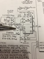
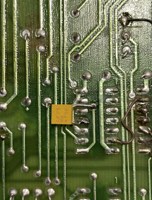
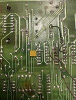
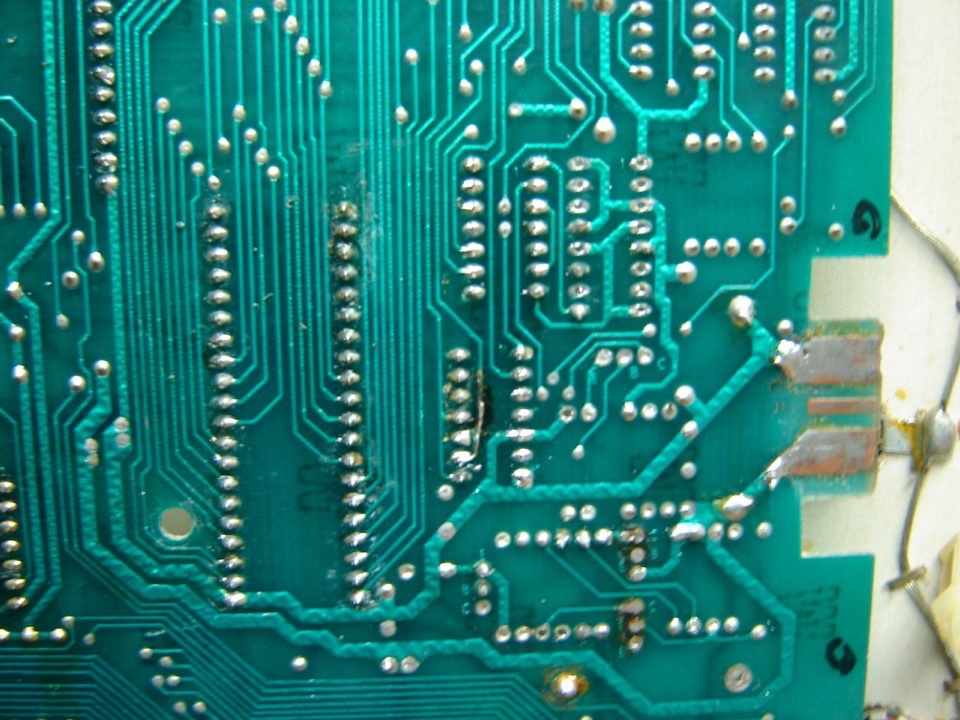
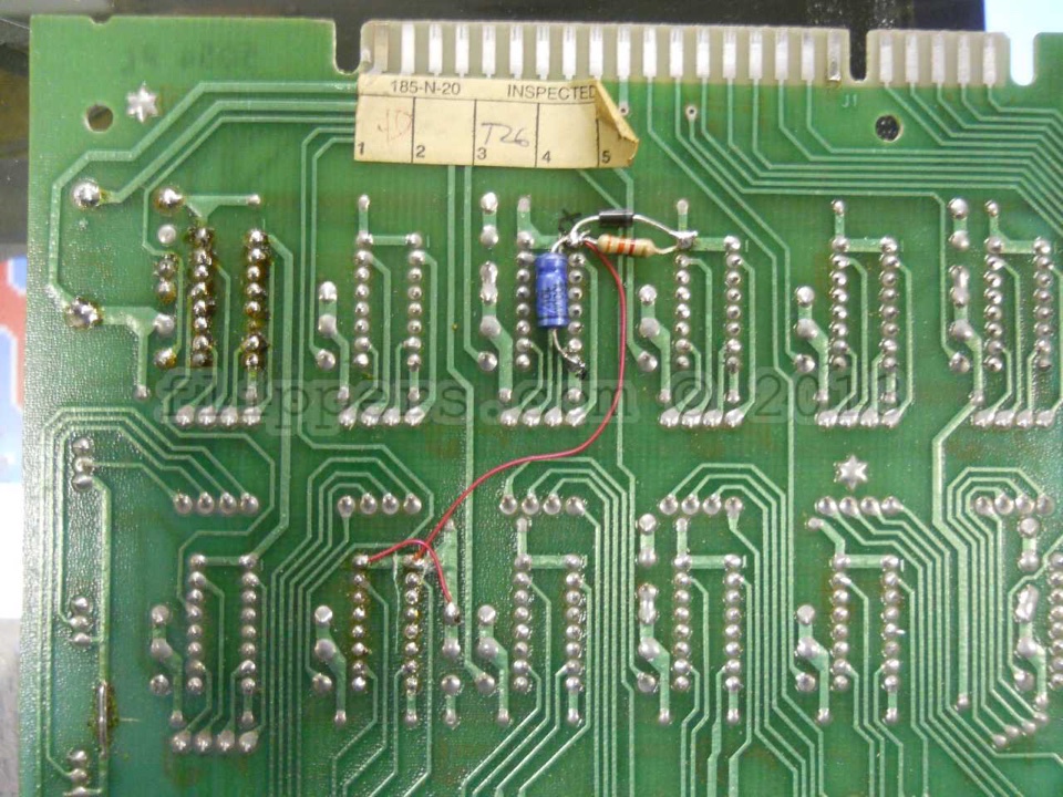
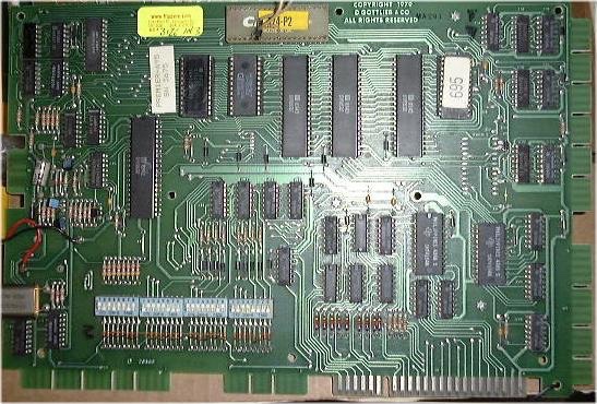
| (Last edited October 13, 2024) Gottlieb System 80(MPU)/A (Eprom and U2(X0) and U3(X1) are socketed)/B Electronic games Subject: Sound/Speech (A6) audio board Not Booting Reliably Subject: Add fuse to small transformer in early System 80 games. Subject: Recommended Gottlieb System 80 (A/B/etc) Ground cures (Replay article 1987) Subject: Modifying Early System 80 MPU boards from two 7461 PROMs to a single 2716 EPROM. Subject: Early System 80 MPU has CMOS Memory problems. (Recommended upgrade) Subject: Protect your sound board from expensive damage. (Recommended upgrade) Subject: TECH: Recharge those displays! Subject: De-Thunk Gottlieb System 80 (A/B/etc) Curing the coil "THUNK" that many games emit on power up (Haunted House, Mars, Black Hole, etc) Subject: Gottlieb's Black Hole, some tips.. Subject: Game is locked up at power-up Subject: Game does not respond to switches, nor are controlled lights running - looks OK otherwise. This applied to a "Freddie" System 3 series game, and the problem was an open fuse @ F6 - looked good, but showed open with a meter. Gottlieb Sound/Speech Board (A6) (schematic E-20921)- not starting reliably, remains silent or makes odd noises. This problem has bugged me for decades and I finally got around to looking into fixing it. Found a TI document on how Powerup for Clock circuits can lead to disallowed states and that was describing the issue - the Clock Divider was not always outputting 900 KHZ, sometimes it would put out 4MHZ or more. So I ended up adding a 47PF (470) capacitor across the Clock and /Q2 output and it solved the problem. Nice stable clock! So if your sound board is not booting reliably add the cap as shown in the photos. John :-#)#
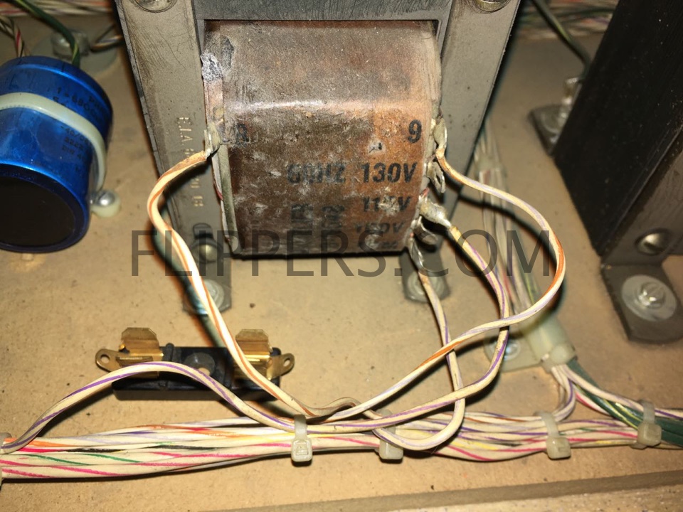
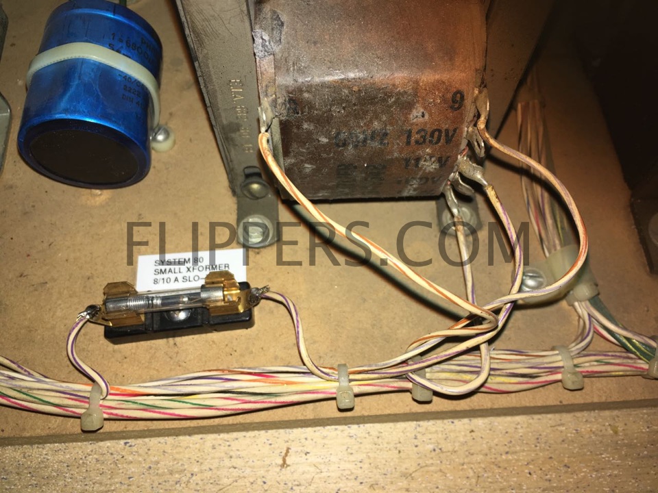
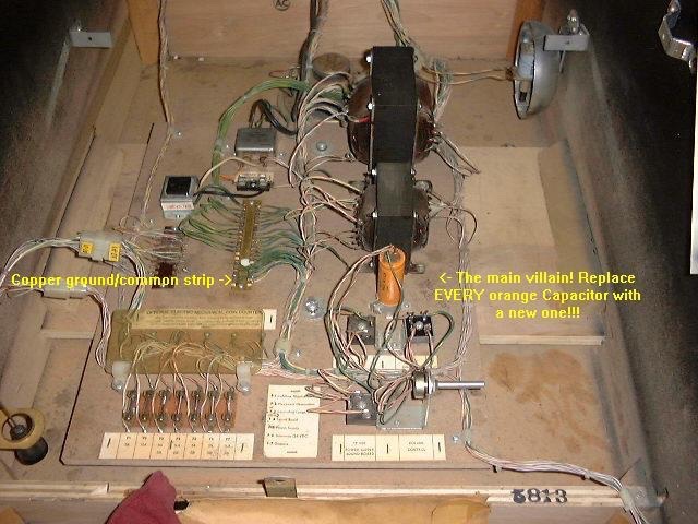
All you need is a 8/10A Slo-Blo (MDL) fuse and a fuse holder and basic soldering skills...
To start -identify the line power wire - in the above photo it is the wire connected to the 120V lug middle-right.
Next cut that line and add the fuse holder, and put a label down too...and you are done!
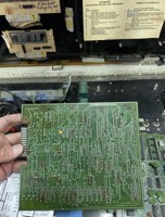
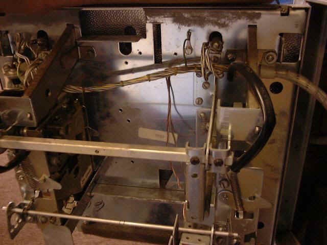
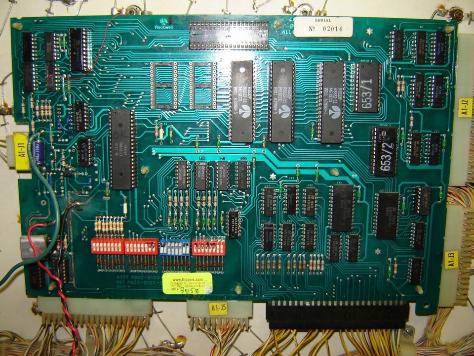
 (Click on image for blow-up) Gottlieb System 1/80(X) series -Ground Problem areas. This was the letter that I sent back in 1987 to Mylstar/Premier/Gottlieb, and was published in Replay, & Playmeter outlining my early research and suggested cures for the Ground Problems found in their games. Additional Ground problem information: An additional suggestion is to use the ground hole on the CPU board (note the Phillips head screw in the middle of picture) that is on the later boards at the 3:00 O'clock position on the CPU board about 2 inches in from the right. This hole has been modified so that it can act as a ground point, and we connect a bolt and nut, and then with a wing nut or screw and jumper wire it to the cabinet ground via the green wire that grounds the lock on the inside of the headboard. Also a modification to the power supplies helps. Connect a jumper from the ground line on either the System 1 or System 80 supply to the frame of the supply then connect a ground wire from the frame to the cabinet ground. This greatly improves the reliability!
Note to recharge the 4-digit displays use only 8V maximum. (JR) Game Locked Up on Power UP System 1/80/80A/80B - Symptom: Game is turned on and displays immediately come up with "000000", plus the displays flicker in a rolling scroll sideways and the start switch does nothing.
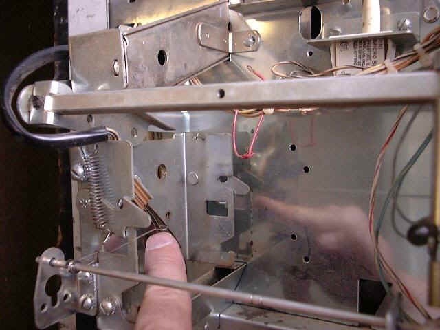
Here is the lockout wire jammed into the coin switch: note that the metal loop is stuck in the blade switch.
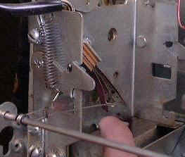
And this is what it should look like (note this door is missing the coin switch actuator wire form): metal loop is free.
Converting System 80 MPU (Control Board) from two 7641 PROMs to a single 2716 EPROM, for early System 80 games like Spiderman A.) Component Side of Control Board 1).Cut trace extending to the left from between pins 6 & 7 of IC Z-10. B.) Non-Component Side of Board 2.) Jumper IC Z-10 pin 13 to the pad located just below and to the right of IC Z-9 pin 7. 3.) Cut traces leading to PROM socket 1 pins 21 and 19. 4.) Jump PROM socket 1 pin 21 to PROM socket 2 pin 24. 5.) Jump PROM socket 1 pin 22 to PROM socket 2 pin 18. 6.) Jump PROM socket 1 pin 19 to PROM socket 2 pin 21, and you are finished. PROM socket 1 is now wired to accept 2716 EPROMs. Now try it out!. Hope this is clearer now...I'll add some pictures if need be. Early System 80 MPU boards have a R/W (Read/Write) timing design flaw (Spiderman, Counterforce, and a few others). These are identified by having TWO PROMs for the Game Memory (often 2 Black plastic ICs) with the GAME number and a '1' or '2' printed on them. James Bond and a few later games might also have this problem as well. What happened is a timing error was built in to the board for accessing the CMOS RAM (5101) and this prevented the MPU from writing data to the last spot on the CMOS RAM. Now in most cases this doesn't matter at all, but if you are testing the MPU and your test equipment indicates that the CMOS RAM can not be written to at location 1FFFh, or fails when you are sure it is good, then you need to do the following minor change. That's all! Now the CMOS R/W timing is correct and you can run the external test fixtures (Fluke 9010 with 6502 pod or the Great Plains System 80/A/B device). System 80 (and System 1) simple 6503 CPU sound boards have a potential problem with input lines that can destroy the 6530 RAM/ROM/IO/Timer IC and these are very rare and expensive to replace. A simple protection circuit that can be added is to tie each of the outputs of the 7404 IC to a 1N400X diode and tie the anode end (banded) of each diode to Vcc (+5VDC) on the sound board. I also recommend adding both a Surge Suppression Diode (1N5908 suggested) and a Ground Wire to the board to further protect it from voltage spikes. 5 X 1N400X diodes are required for this. See pictures below for the positions to add them to. 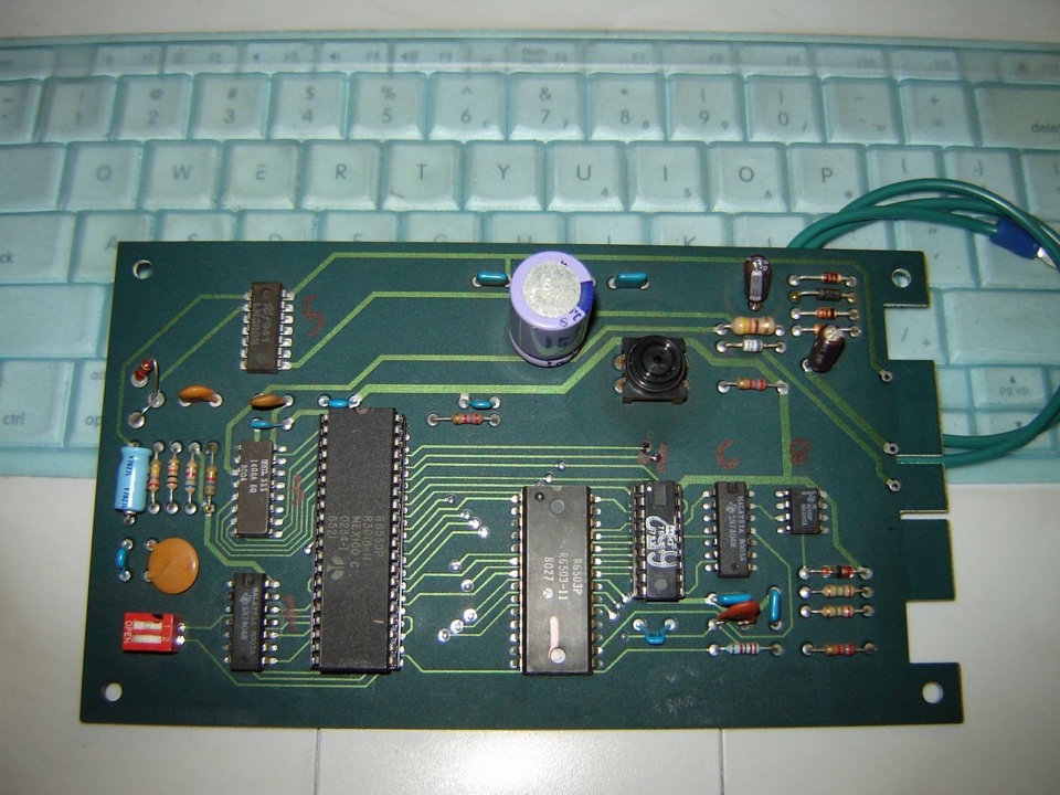 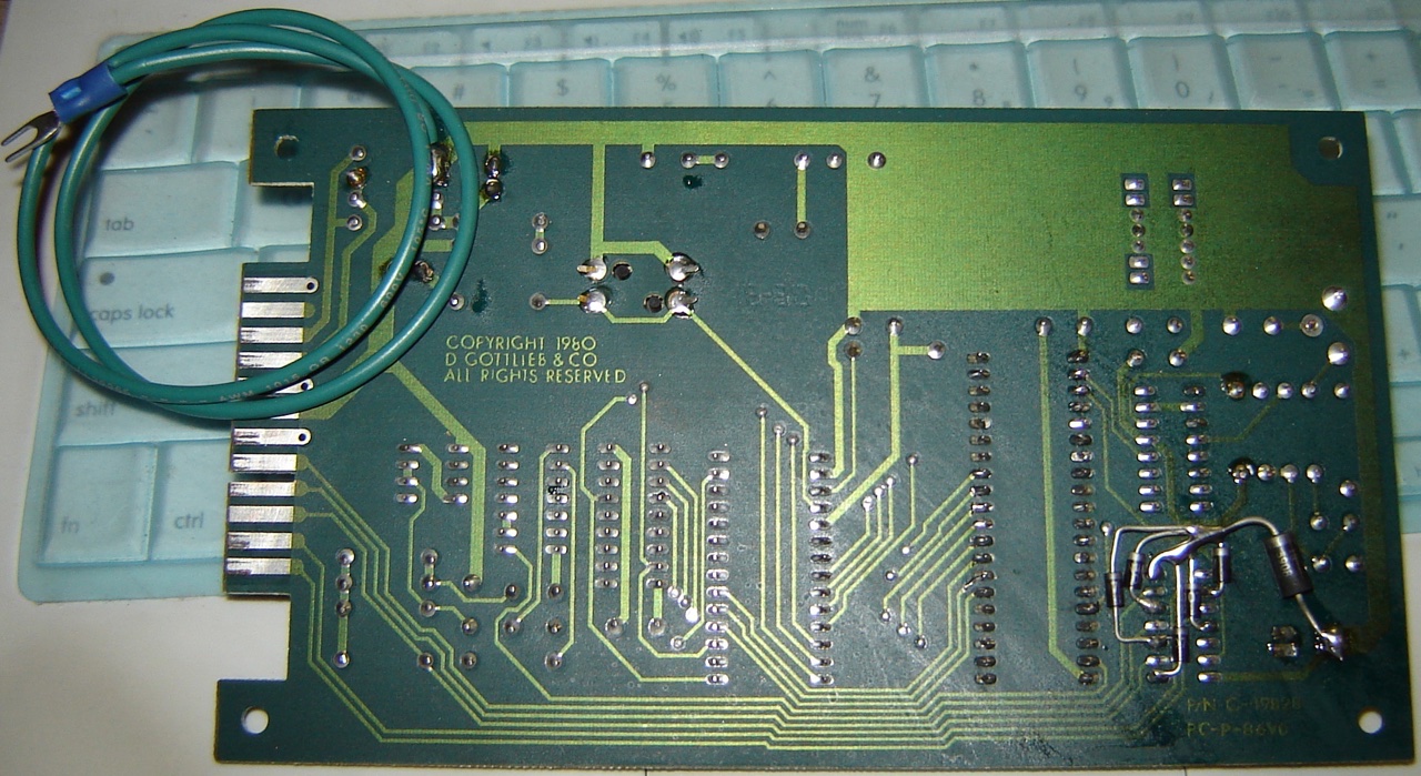 Thunk! Ah, the dreaded THUNK noise that happens often when the game is turned on! Actually the cause is quite simple. Gottlieb, in their wisdom (?), had Rockwell design the circuit boards for their pinball games and in doing so the "engineers" (must be a Dilbert Zone) neglected to read the recommendation from one of the IC manufacturers. Namely the SN74175N IC's. There is a "Clear" function on these IC's that is used to set the outputs to a known state, and is supposed to be used to make sure the outputs don't turn on in an indeterminate state. Unfortunately Rockwell (or whoever) in their design, decided to simply connect this line to the +5VDC bus. Thus when the game is turned on the outputs are sometimes LOW or sometimes HIGH, and hence the "THUNK". The cure is not too difficult: 1.) For Black Hole you only need to do two of the 74175s - IC Z3 (lower Ball Gate) & Z4 (Lower Hole Kicker, Outhole, Lower Ball Lift Kicker, and Ball Release). Carefully clip the CLEAR leg (pin 1) at the circuit board, bend it up and over the back of the 74175. Or on the rear of the PCB isolate pin 1 of Z3 and Z4 (Z5 if you wish too) by cutting the trace and connect the isolated pin 1s together and to the added reset circuit (#3 below). 2.) Next run a small jumper wire between the bent up legs, I recommend that Z3, Z4, and Z5 are done if you aren't sure about your game. 3.) You now need to make a simple RESET circuit for the 74175's. You will require a 10K 1/4w resistor, a 100ufd/10VDC capacitor and a 1N4001 (any 1N4001 - 1N4007 is fine) diode. 4.) Connect one end of the resistor to +5, the other to the + lead on the Cap. The negative lead of the cap goes to ground. Vcc---/\/\/\/----|---|(---Gnd 5.) Now hook the diode so the band end of the diode is connected to +5VDC and the other end is connected to the junction of the resistor & capacitor. Vcc---/\/\/\/----|---|(---Gnd 6.) Lastly connect the junction of the three (Resistor/Capacitor/Diode) to the line connecting Pin1 of the 74175's. Vcc---/\/\/\/----|---|(---Gnd Done! NO more THUNK. Good work. Oh, and while you are in there, why not do the Ground Fault fixes? An improvement for Black Hole: First, to reduce wear and tear on the spin motor we recommend |


(jrr-at-flippers-dot-com for those who do not have their browser set to open their email client) |
