|
|
|||
| site search by freefind |
Servicing the Tormat Selection Receiver (TSRx series) Ron Rich's Fuse Recommendations... Seeburg Jukebox Service by Tony Miklos Lubrication - only use 20 weight motor oil (20W)! Blue Top Three-In-One/3-In-1 is good, the Red/Black top is no for machines. Zoom Spout is usually good too. Do not use WD 40 or Aero Lubriplate as they turn to goo/glue over time! Great Seeburg resource guides! - The first PDF (click here) is for servicing SHP and TSA series amplifiers , the second PDF is Digital Troubleshooting the electronic selection system (black & grey boxes). These were from a company called Hudsons Bay Vending which operated 100's of Seeburg jukeboxes across Canada back in the the day...the author was Karl Jones. Ron Rich says: "The "test lamp" consisted of a NE 51H, lamp, "selected" to light at 6 volts dc, with a33 k resistor in series." So, now you know how to make your own Seeburg Test Lamp. I (John) use one of the two lead neon bulb test lamps you can still buy at hardware stores...they work pretty well for doing the Seeburg tests. Ron Rich says (edited by JR):To update either a 45 TASU-1, or -2 AUTO-SPEED to a code C unit add, if not there, a 1.0 x 200V mylar capacitor to each of the two transistors between Collector & Base terminals. Also, add a short jumper wire between the speed control CASE, to the common grounds on the relay contacts (black wires) as there are schematics that show this ground on the wiper side --wrong-- that would short out the control! New page - Seeburg Service Bulletins! I'm uploading 1950s service bulletins when I have time... Typical lubrication points (PDF) for the Seeburg mechanism.... How to remove the red 'tailight' dome lens covers from models KD200 & 201 to replace the light bulb (#55 or a #455 for flashing): 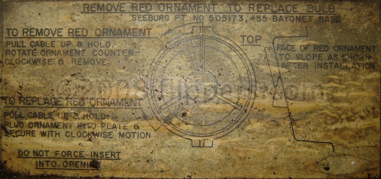 201 - lift lid, then lift the wire (covered in black plastic) enough that the dome will turn about 1/8 rotation counterclockwise. 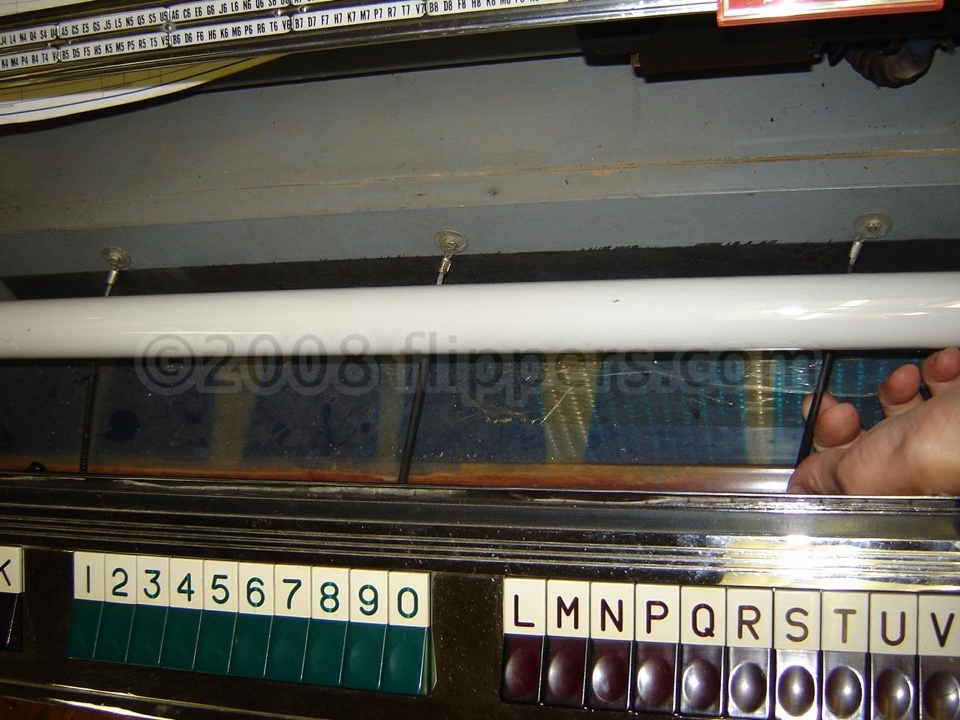 KD 200 - lift lid, lift keyboard forward, lift keyboard again to get past stop so it lays down completely forward, then lift one of the three wires the same as for the 201 above (no plastic tubing on these wires): 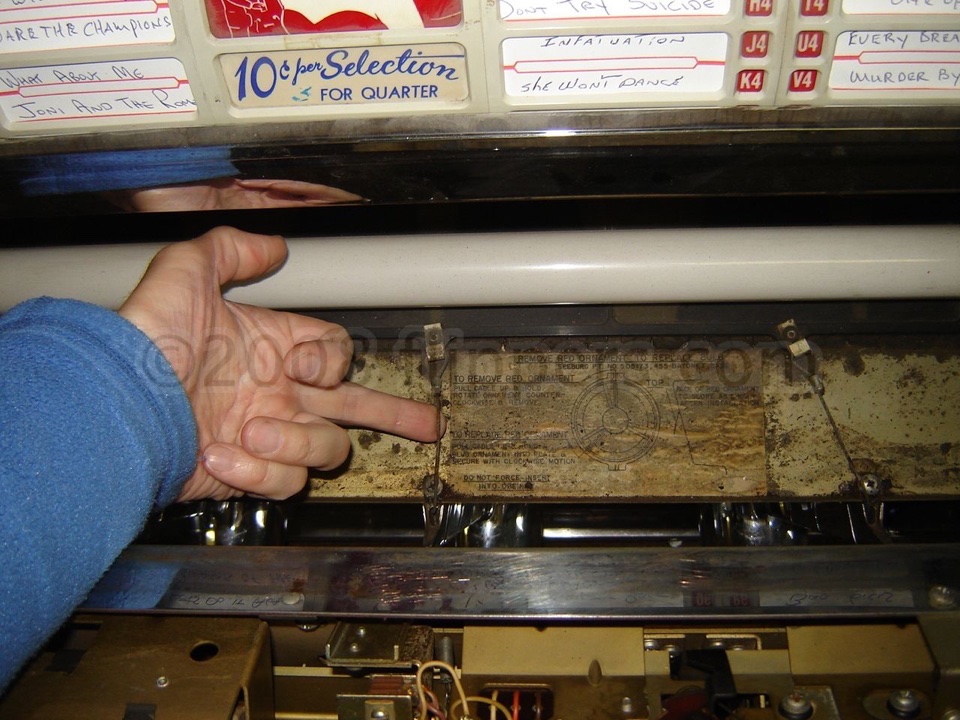
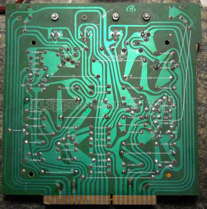
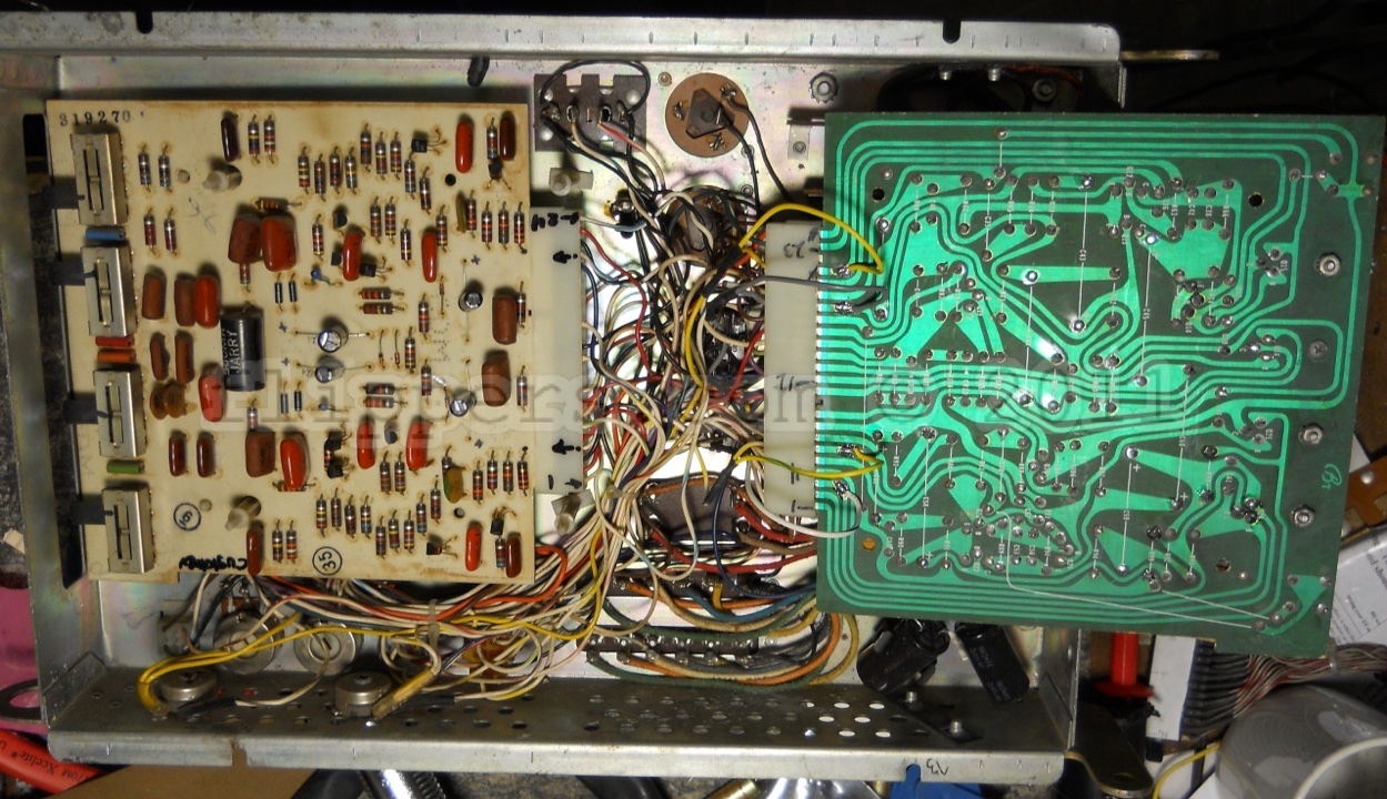
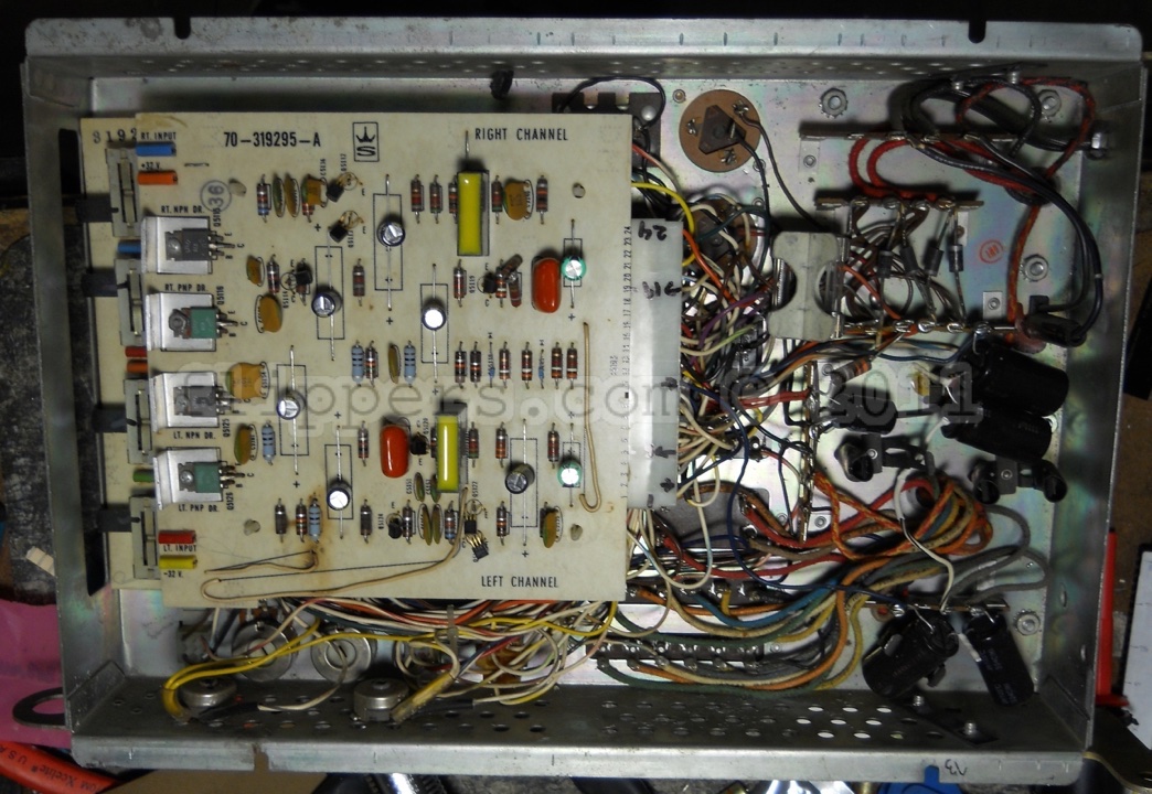
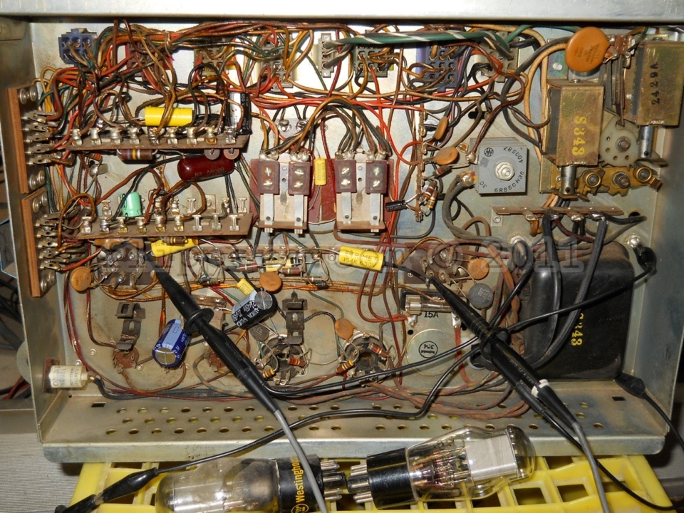
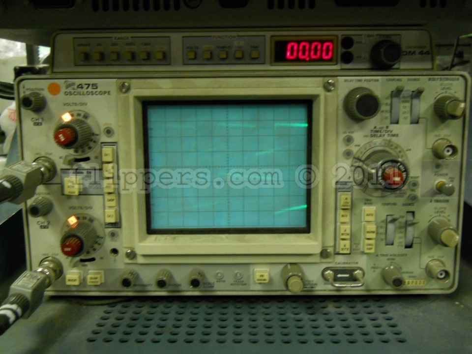
Servicing the Seeburg tube style Tormat readout(under construction)
The following was written by Ron Rich from Jukebox Addicts - Ron Rich's online forum. Ron passed away in 2023 and is sorely missed. Gentz,
FUSING SUGGESTIONS !!!!!! (click for original link - you need to join to see the post)
Since Seeburg was so stingy on "fusing" here are some suggestions to better protect the mostly NA transformers, AND the wiring that catches fire ( maybe the cabinets too !)
EDIT:(Ron Rich) The power transformer for the TSR/TSU series units may still be available-- contact me, if you need one.
--by Rob/NYC
25 VAC: 4 amp-slo
150 VAC (thyratron tube plates) 1 amp-fast 5 VAC (decorative lights) 3 or 4 amp-slo, you can use less if only a few lights such as a model 201..** 6.3 Volt tube heaters, I use 5 amp-slow The HFMA1 draws a just over 3 amps for heaters. By me--
--on "fusing"-- The M-100 and HF 100 series SAU ("pinbank") type, phonos, when using a WSR-5, have paper markings as to fuse sizes-- The "main" fuse, if only one display florescent lamp is used, should be a 3 A FB. If the pilasters are also lit, and motorized, use a 5 A FB. Also, IMHO, a good idea to fuse the motor only, at 1 A FB. The "CCU fuse", is marked "2 A,SB". --this IS, too high, and WILL allow, SAU coils to burn up--MAX on this fuse is 1.6 SB ! --I attempt to use a 1.0, SB, or slightly higher value (NOTE: the fuse clip holding this fuse tends to "become weak", and often should be replaced !). I also fuse the "cancel coils/pop meter coils" at 1/2 ( if no pop meter coil is connected,1/4 amp)--SB. WSR-7, as marked on chassis, except the 1 a SB fuse is, and should remain a 1 amp.
On the TUBE, type Tormat units--Split off the transformer AFTER, the main 5 A, MTH fuse--use a 2.5--3 A, SB type fuse here ! Use a 1/2 amp SB on the rectifier, if you change it ( also true on SAU type phono's ). Add a 3 amp FB fuse AT, the latch bar solenoid, "hot" side, probably not needed, IF, an electronic "free play unit" (STRONGLY SUGGESTED !!)-(not the "cheapie", plug only, type !), is used, but it won't hurt ! If not there-- add a 2 amp SB to the primary side of the transformer circuit for the 5U4 in the amplifier, if not already there. Add a 1 amp FB in series with the the Detent/Trip coil-- these coils are getting very hard to get ( "250 ohms", and are NOT the same, as on other models 6 + ohms) !
On the Solid State phono's-- Change the 15 amp fuse in the control center to a 7.5 A--MAX ( true also of the TCC equipped phono's--)(most will operate fine with a 5 A FB). Latch bar suggestions, same as above.
On the "MicroLog" models--SEE my MicroLog trouble shooting guide, as fuse size varies from one model to the next ! --be sure the fuse in the snap holder, by the transformer, does NOT exceed 7.5 A,FB !
On SMC models--- Reduce the main fuse to 5 amps, reduce the 6/10 (motor fuse) to 1/2.
On ALL "SHP type" amplifiers-- Reduce the main fuse ( either a "Red-cap", or "normal" style) to 2 amps SB
** Note: This is the "main" ( and on Tube type, Tormat units, the only ) fuse in the phono for the WSR or TSR/TSU equipped phono's !!(RR)
"N"type (3.2 amp, in Seeburg's case) fuses are dangerous ! If good, or in some other cases, the tops of this type fuse has power on it at all times !
There is also a very slim chance a transformer has shorted, and has full 117 VAC on that metal exposed tab-- BE CAREFUL !!
BTW--NONE, of the above, should not be considered as a positive, sure thing, that will prevent damage--it should do so, but, no gar-un teez !!
HTH---
Ron Rich
<Top> Jukebox trouble shootingTwo problems common to virtually all Seeburg vertical play record mechanisms are independent of the selection system used in the jukebox. There is another problem common to all mechanisms using the Tormat Memory Unit. I'll give pointers to fixes for all three below. Please note that while I have checked and rechecked to insure that the below information is correct, I take no responsibility for any difficulties incurred as a result of performing any operations listed.Symptoms
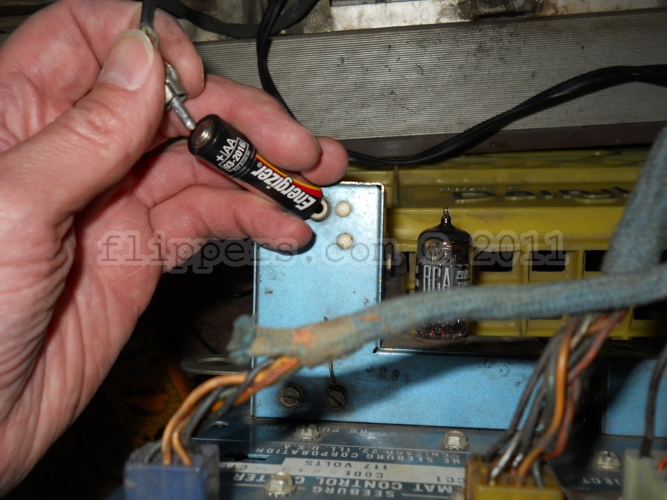
Disconnect the RCA plug sense loop connector from control center or selection receiver. Connect the negative side of a C or D cell battery to the center pin of the plug, while grounding the positive side of the battery to set all toroids to the selected state. (Note that if you use this procedure on a tube-type jukebox, you must reverse the battery connections.) Plug the sense loop connector back in and manually scan the mechanism. It should now trip at each record, transfer, and play it. Upon reject, the mechanism will move to the next record, and repeat the cycle. If this does not occur, the problem is in the Read-Out or Trip Circuits. If operation is normal, the problem is in the Write-In circuits, to be covered later. Read-Out or Trip?If the problem is in Read-Out or Trip, we must continue to eliminate one or the other. First, verify that the Read-Out timing is correct. Turn the machine off and disconnect the mechanism plug from the control center or selection receiver. Move the carriage to one end of the magazine, remove the records at that end and also remove the mechanism carriage cover. Set your ohmmeter for continuity and connect it between L1100 and ground. This is the inductor that is mounted to the Detent Timing switch next to the motor. Either side of the inductor will do and any decent ground should do. Slowly rotate either the turntable or the motor coupling a small amount and note which way the carriage moves. Now check the Contact Block Actuator slide or reversing switch (depending on jukebox model) to make sure that it is in the correct position for the direction of carriage travel you have chosen. Note that some models (most notably, LPC1 and LPC480) only perform Read-Out while traveling in one direction. For those models, make sure you are moving the carriage in the Read-Out direction. Slowly move the carriage until you get continuity, then stop. Now if you sight down between the metal record separators, you should see the Transfer Arm Head perfectly lined up with (centered on) the magazine record separator. If so, the timing is correct for this direction of travel. If not, fix it. There are several inter-dependent mechanism adjustments which affect this timing. They include: Magazine - Horizontal Position, Transfer Arm 1, Tormat Memory Unit Position, Read-Out Contact Block 1, 3, and Detent Switch. Any one not correct will make this timing incorrect. Perform this check at each end of the magazine and in each direction for those machines doing Read-Out in both directions. Once the adjustments are correct, an overall indication of correct Read-Out functionality can be determined by connecting the correct polarity probe of an analog voltmeter set for voltage on the 200-400 VDC scale to the 'Read-Out Source/Read-Out Load' terminals of the control center or selection receiver. The other probe should be connected to ground. Plug the mechanism cable back in, apply power, and start the scan. You should see your meter dipping from the high voltage while the carriage is in the magazine area, and a steady high voltage (which should be approximately equal to the Write-In voltage) at the magazine ends while reversing direction. The dip occurs each time a toroid is read out. While in the magazine area, you should get a voltage reading of between one-third and one-half the voltage read at the magazine ends, with the voltages equal while moving in both directions. For the digital machines, this voltage should be between +55 and +60 VDC. Note that a digital voltmeter will not help here. If the voltage reading is constant, there is a broken connection between this test terminal, the mechanism Detent Timing switch, the contact block, the Tormat rivet connections, and ground. If you measure zero or significantly less than the Write-In voltage, the problem is in the control center or selection receiver power supply or wiring. If the voltage reading is off in one direction but not the other, the problem is usually caused by a bent or pitted contact block contact, or a misaligned Tormat. If the voltage reading is low or high in both directions, re-adjusting the Detent Timing Switch should solve it, but keep in mind that dirt or pitting on these contacts could result in a valid voltage reading but not enough current to Read-Out the toroids. If you are using a neon indicator connected in place of the shorting link between the 'Read Out Source' and Read Out Load' terminals of your control center, you can get a correct indication (neon lamp flickering) but no Read-out due to dirty or pitted contacts. If your box has the symptom that selects properly in one direction but not the other, and these readings are correct for the good direction and not the other, suspect a broken or mis-adjusted contact block contact for that direction. It is also possible that the contact block is not making contact on one side of the Tormat due to worn carriage rollers. If your readings are correct and there is still no trip, the problem is in the Trip circuit. Thanks and a tip of the hat to Ron Rich for contributing to this section. Trip Circuit ProblemsIf you've gotten to this point, the problem is in the trip circuit. The next thing to do is to eliminate either the Select Trip Relay or the trip circuit, which may use either a thyratron or SCS as the active device. Unplugging the RCA plug and plugging it back in while the mechanism is in scan will usually cause a trip to occur due to the noise induced as you disconnect and reconnect the RCA plug. You should be able to force a trip by connecting the positive end of a C or D cell to the gate of the Trip SCS, with the negative end of the battery grounded. If this is the case, the Trip circuit is probably okay (check the input components to make sure) and the problem is most likely an open sense loop or intermittent RCA plug connection (see below). The control center or selection receiver should have a set of three adjacent screw terminals, marked 'Read-Out Source', 'Read-Out Load', and 'Trip Relay'. Note that several of the 100 selection control centers do not have the 'Trip Relay' test point. The first two should be connected by a shorting link. Turn off the power and loosen the screws securing the link. Rotate the link so that it now connects the 'Read-Out Load' and 'Trip Relay' terminals, and tighten both screws. Re-apply power and manually place the mechanism into scan. It should now trip at each record, play it, go back into scan, trip at the next record, etc. If this does not occur, the problem is in the Select trip Relay, Trip Solenoid, mechanism switches 2M11, 3M1, or the associated wiring. If the trip/play/reject cycle functions normally, the problem is with the Trip circuits. A very good possibility to check is the sense loop RCA connector, especially the ground contact between this connector and the PC board. If your machine uses the Pulse Amplifier, check the resistors and capacitors inside for changed values due to aging. Another possibility is a broken wire in the sense loop. For the solid state machines, check the resistors and capacitor in the SCS gate circuit for correct values. The sensitivity of the SCS gate is partially determined by its anode voltage, so check to insure that the SCS power supply (usually +27 VDC) is correct. For the solid state machines, check for a bad ground connection between the RCA jack and the control center chassis, and also check continuity between this jack and the trip circuitry on the control center PC board. Check for continuity between the RCA plug center pin and shield. This should measure no more than a few ohms. If you do not get continuity, the plug itself is the most likely culprit. The Tormat has no moving parts inside, so theoretically nothing should go wrong. It is possible, however, that some of the wires may have gotten frayed over the years. If so, the most likely place is where the cables exit the Tormat. To gain access, remove the four screws holding the cover to the ends of the Tormat. The black plastic contact rivet memory block at the end opposite the cable exit is screwed to the metal baseplate using two screws. After you remove these and the screws holding the cover, you can gently remove the memory block, followed by the cover itself. Be careful that you do not snag any wires when removing or replacing the cover. Obviously, the warranty is no longer in effect. Write-In Circuit ProblemsHere's how to determine if you have a problem in the Write-In circuit. If your machine uses a remote control stepper and it can be bypassed, do so by disconnecting the Tormat cables from the stepper and connecting them together. Connect your analog voltmeter to the control center or selection receiver test terminal marked 'Write-In source' and ground, being sure to observe the proper polarity for your machine. Establish credit and make a selection. You should see the voltage at this point momentarily dip as the write-in capacitor is discharged through the Write-In triggering device and the selected Tormat Write-In loops, followed by the voltage slowly building up again as this capacitor charges. If the measured steady-state voltage is significantly lower than the expected voltage discussed above, the problem is in the control center or selection receiver power supply circuitry, a leaky Write-In capacitor, etc. Try to isolate the power supply by unplugging the gray box (black/gray box jukes), Write-In relay (red box jukes) or Pricing Unit (all others). If the low voltage still remains, the problem is in the power supply. Otherwise the problem is in the Pricing Unit or selection circuitry. If the Write-In triggering device is shorted or some other current path to ground exists, or there is a problem in the stepper (if your machine uses one and you cannot bypass it) the Write-In voltage will go to some lower value once the connections are re-established. Won't make any selectionsIf the Write-In voltage is correct but doesn't dip for any selection, the problem is in the triggering device, pulse-forming network, or the Tormat ground return. For the tube and non-digital solid-state machines, the triggering device is the segmented switch located in the Pricing Unit. This switch is closed as the subtract solenoid energizes. For the black/gray box machines, the triggering device is the Main Trigger Silicon Controlled Switch (SCS) located in the Gray box. The red box machines use a Write-In relay, located in the Phono Power Center. If the voltage never dips, this means that the Write-In circuit has not been completed to ground. Check the triggering device first, followed by the pulse-forming network. All machines use a network to shape the Write-In pulse. This circuit consists of several inductors, capacitors, resistors, and a voltage clamping device. The network is wired between the triggering device and the selection circuits and can be found in the control center or selection receiver for all machines except the black/gray box jukes, where it is in the gray box. The voltage clamping device will be either a diode or a zener diode, which clamps the Write-In pulse so that its amplitude cannot exceed one-half the Write-In supply. The tube-type machines use a diode connected to the junction of the OA2 regulators to clamp the voltage to -150 VDC. The solid state machines use either a diode to the bottom capacitor of the voltage doubler, or a zener rated at one-half the Write-In voltage. The final suspect is the Tormat ground return, which is typically connected through a temperature compensating resistor, located in the Tormat. Note that only some of the Write-In loops common to this resistor. Using your ohmmeter, check for 190 ohms (earlier machines) or 72 ohms (later) to ground through the pins of the Tormat connector which route the Write-In loops to the resistor. Here's where having the manual for the machine comes in handy. There will usually be a simplified Write-In circuit diagram which will identify which loops common through the resistor. If you get this reading on none of the pins, the resistor or the connection is probably open. Not getting the reading on one pin implies that loop is open. Keep in mind that the ground return to the control center or selection receiver is sometimes made through this same cable, so make sure you check for continuity all the way back. Also remember that some machines have a shorting link in the control center or selection receiver which completes the ground return. Missing or additional selectionsSuccessfully making some selections but not others indicates a problem in the selection circuits themselves. All non-digital machines use a latched push-button selector in which the depressed push buttons each complete a current path through the Tormat. Poor contact on these switches or the connectors between the selector and the Tormat could be the cause of the problem. Clean, adjust, and lubricate as necessary to correct the problem. The digital machines use SCSs to complete these paths, and there could be a problem in one or more of these circuits. They are located in the gray or red boxes, depending on type of machine. Remember that all machines must complete a pair of Write-In circuits (letter/number or (hundreds/)tens/units digits) for a toroid to be selected. If one path is complete but the other isn't, Write-In will not occur. Each of the two paths consists of the selection device, one or more cable connections between the device and the Tormat, the loop of wire through the toroids, and a common connection which either goes back to the selector or through the temperature compensating resistor, depending upon machine and selection loop. Any open or high resistance connection here can cause the problem. By making several selections, you should be able to see a pattern emerging which should lead you to the faulty circuit. For example, if you cannot make any selection with '5' as the number or units digit, suspect the circuitry associated with that digit. Latched push-button selectors have each button wired in sequence from the one before it. Pushing a button disconnects the circuit from the remaining buttons, redirecting the Write-In current to the selected circuit. Suspect a problem in the sequencing circuits (which are links between switches on the selector push button assemblies) if you cannot get any selection greater than a specific number or letter. Another possibility is that you get a different selection, or one in addition to the one you made. This generally happens only on the digital machines, and is usually caused by an overly sensitive SCS firing instead of (first case) or in addition to (second case) the correct one. My book gives a procedure to follow to determine the cause of Write-In problems in the gray box. If this problem occurs on the other machines, suspect a sneak path through the Tormat (perhaps caused by frayed wires inside), an incorrectly wired selector/Tormat (this should have been caught years ago unless someone has recently been digging into your machine), or a problem in your stepper. Perhaps the best way to track this one down is to (armed with the simplified Write-In schematic from the manual) check the continuity between the pulse-forming network, the selection device, and the Tormat to the common connection for each loop. For a 100 selection machine, there will be twenty such circuits; the 160 machines have twenty eight, and the 200 selection machines have thirty. Make sure you do this with the power off! |
||||||||||||||||||||||
(jrr-at-flippers-dot-com for those who do not have their browser set to open their email client) |
 Click here to order Parts