|
 Click here to order Parts
|
|||
| site search by freefind |
(If you don't see the Google Translate's "Select Language", then your browser is blocking google translate...so enable googleapis.com)
ALI Tips Page...as of March 31, 2025
Menu:
1) Repair Tips
2) Testing Power Supply
3) Fuse Holders
4) Switch Problems?
5)
Game not booting? Check Reset Capacitor!
5) Self Test Procedure (added May 30, 2023) and Service Bulletins
I have finally compiled the complete set of schematics and troubleshooting guide for the 1st generation Allied Leisure Industries (Florida) pinball games that used a number of separate logic boards.
Lets call that System 1 - 1975. System 1 did not have a CPU, rather it is a collection of 10 or so circuit boards that makes up the logic for the games.
There were only three games made that used System 1 (as far as I know...):
- Rock-On (4 player)
- Boogie (4 player)
- Dyn-O-Mite (2 player)
All used the same playfield, cabinet artwork, wiring and circuit boards with the only differences being the backglass and if they had two or four players. We can not service any of these three game boards in our shop at this time as we have no test fixture for these multi-board ALI pinballs.
RECOMMENDED SERVICE UPGRADE TO ALL ALI SINGLE (pinball) MPU BOARDS!
Roy Clark Super Picker - The Entertainer, Getaway, Hoe Down, Take Five, Flame of Athens, Hearts Spades, Disco '79, Star Shooter, Eros One, Eros II, and Circa 1933
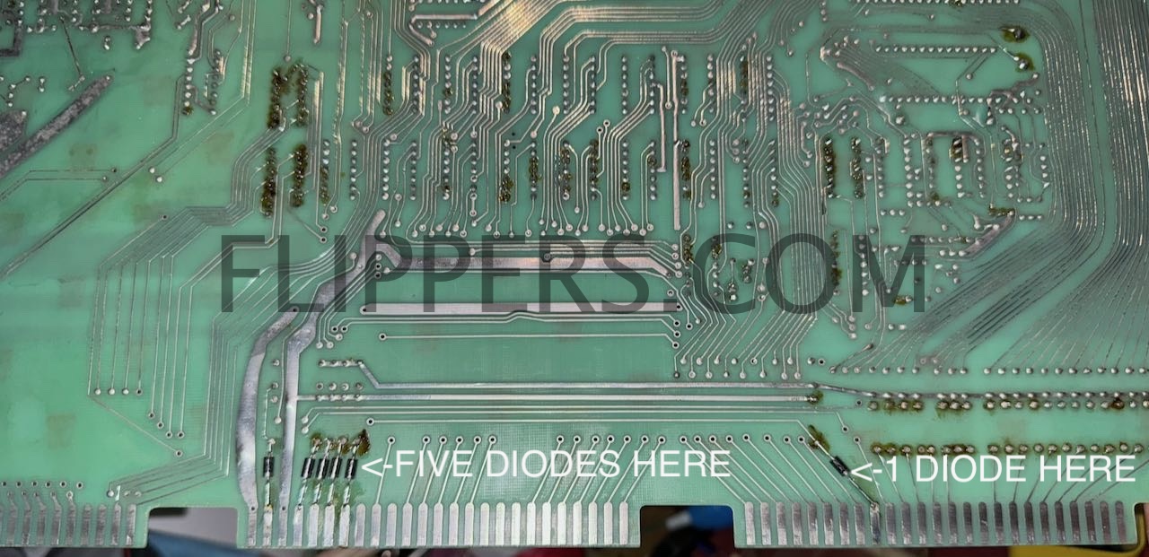
Oct 25, 2024 - We realize that a number of boards have died because of voltage surges to the coin, tilt, test, and start switches and this must stop! Parts blown include either a 6530 ($$) or 6520/6821, and a number of TTL chips.
Look at the photo just below and you will see that we have added 6 of 1N4001 (to 1N4007) diode (banded end to card edge connector - down)after cutting the underlying trace. This isolates the TTL and 6530/6520 logic from the switchs and will greatly reduce the risk of damage to even the earliest boards - which will still need the diode isolation board when finished.
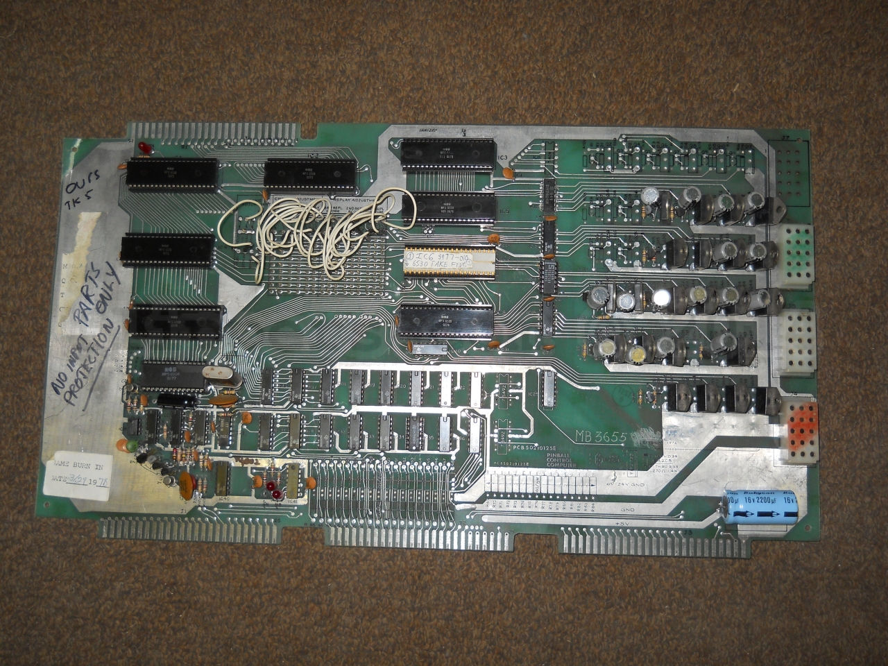
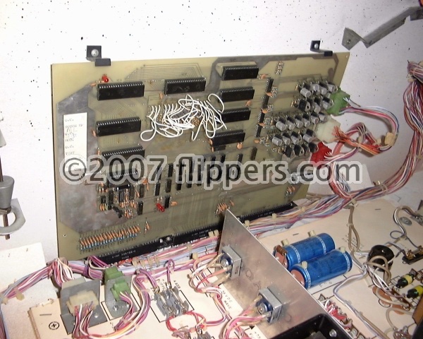
The single MPU board I'm calling System 2 (2A) used a single logic board that originaly had keep-alive resistors for the lamps, PCB50210125 to PCB50210125E (F?, G?) - note this board is NOT RECOMMENDED for use due to the lack of input protection circuitry for custom 6530s (more on upgrading this board later)! The photo shows System 2B MPUs with the resistors not installed by the factory. (not all Rev. E had those keep-alive resistors installed). System 2A can be identified by the card edge connector on the upper left in the first photo below. This card edge connection was removed for the later System 2B, C, and D and a number of extra ICs were added to help protect the 6530s with System 2C & 2D. If you have a System 2B or 2C MPU I recommend adding the 22 input protection diodes, as described below, for all switch lines to help protect the 6530s from electrical shock.
LEDs - if you are replacing the incandesent lights (#44 or #47) with LEDs to your System 2A/B board you have to remove the 36 (35?)Keep-Alive 100 ohm resistors on the bottom of the MPU board. These resistors will otherwise cause your LEDs to all light up! Keep-Alive resistors are there to help keep the filaments of the original incandescent lamps slightly warm so the thermal shock of being turned on would be less stressful for the light bulb. These resistors were dropped in later MPU boards. They are numbered R51-R67, R73-R76, R85-R102
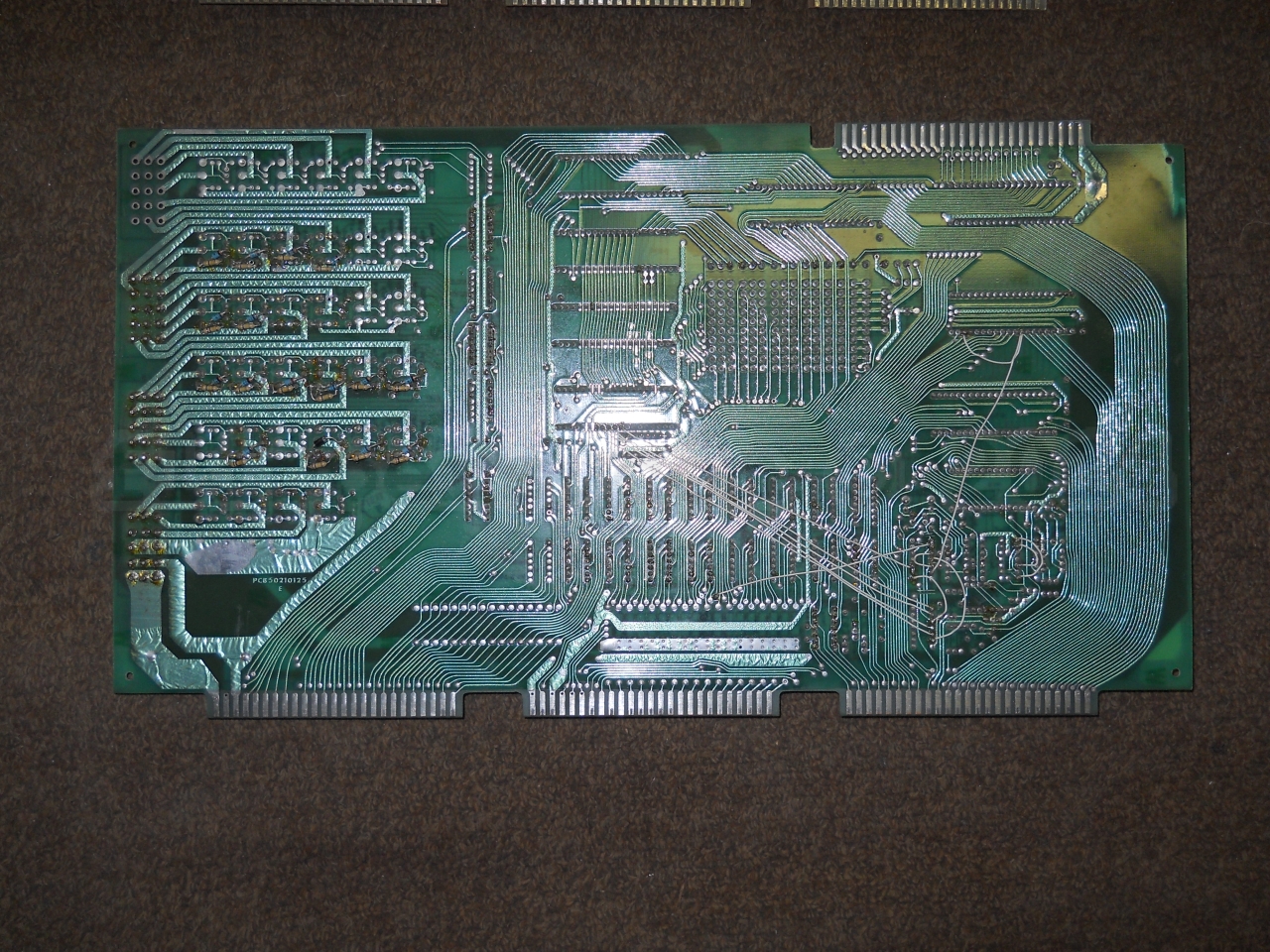
System 2A/B PCB50210125E - note the resistors over the middle 22-pin connector, the unused connector on the upper left, and the jumper wires on the rear. I've not seen boards number PCB50210125F or G...
The plan now is to make an isolation board that fits between the MPU and the three bottom plugs to provide switch input protection for these boards. Almost ready!
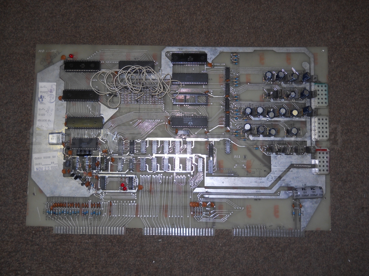
System 2C/D PCB50210125H changed the board design slightly, it had the same basic single board but added input protection for 6530s and had deleted the Keep-Alive resistors and unused driver transistors, upper right card edge connector, etc.. If you have a choice, repair or restore this version or later. Note there is no card edge connection on the upper left of the first photo (on the left) below.
As near as I can tell ALI released four versions of their motherboard (6504 based CPU) PCB50210125 - the PCB50210125E (1st with and 2nd without upper right card edge connector - but no switch input protection) and later PCB50210125H - the first version of "H" had resistors, the second version had 22 diodes to replace R77-R84, R143-R154, R161, & R162. I highly recommend replacing the resistors for diodes, banded end facing the card edge connector. Use 1N4002 (100PIV) or higher rated diodes.
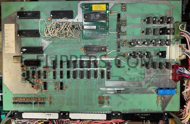
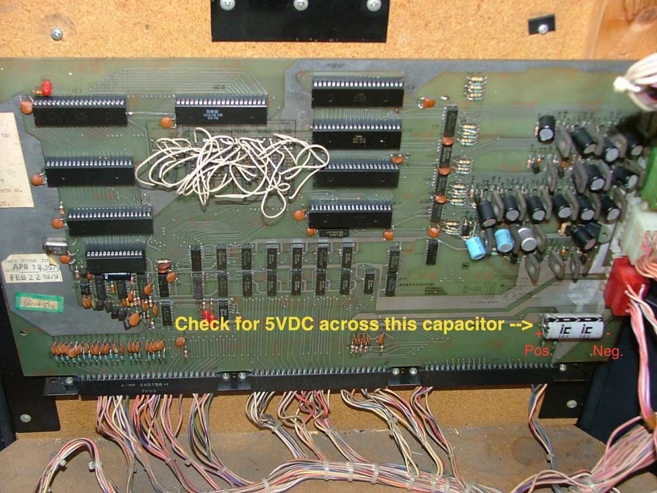
ALI manufactured a number of pinball games all based on one MPU (Central Computer) board as shown below (MPU System 2 & 3). The MPU was powered by a single +5VDC power supply usually located on the bottom of the cabinet. (see below), and you want to make sure it does produce 5VDC (+/- 0.25VDC) at the MPU. You can measure the 5VDC at the filter capacitor mounted on the lower left side of the MPU board (just below the three plastic plugs Green/White/Red on the far lower right of the MPU).
The pinball games made using this MPU (the features - lights, switches and coils - were re-arranged by ALI to change the rules for each game) include: DISCO 79 (c/t), EROS ONE (c/t), HEARTS & SPADES (c/t), HOE DOWN (u/r), ROY CLARK/THE ENTERTAINER (c/t), STAR SHOOTER (c/t), TAKE FIVE (c/t), THUNDERBOLT (u/r), and GETAWAY (u/r). u/r = standard upright pinball. c/t = cocktail style pinball.
We service the MPUs, and also sell manuals, rubber rings, lights, and other parts for these games! Email link at the bottom of the page...
We now (2023) sell rebuilt Revision H MPU boards - click here!
The picture shows a 4th version single MPU game board (Revsion H w/diodes):
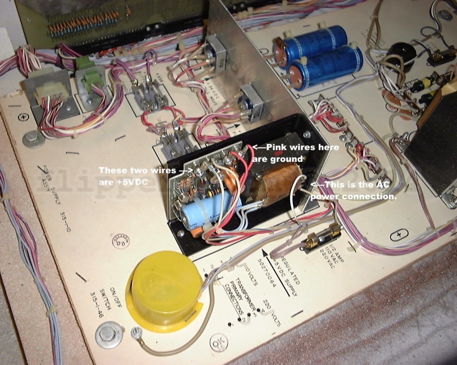
Here (below) is the 5VDC power supply that needs to be checked for proper voltage and that the capacitors are in good condition.
Check for good 5VDC across the main logic board filter capacitor (picture).
Note that linear power supplier like this one can appear to have good 5VDC output when measured with a voltmeter, however you MUST also check if there is any AC ripple by setting your voltmeter to AC and then put the leads across the output terminals - the reading should be 0.00VAC. If it is more than about 0.1VAC then the power supply needs servicing or replacement with a modern switching supply or rebuilt linear (if you want to be authentic).
To verify that your voltmeter is reading AC ripple check that the meter reads 0VAC when connected to a battery (9V or 12V)...
Note too that if you rebuild a linear power supply that you verify the output is 5VDC BEFORE reconnecting the power supply to the wiring harness! I now recommend (2010) that you either rebuild or replace the old Linear power supply with a modern switching 5VDC power supply. Ones that are used for Video Games are quite satisfactory and easy to install. Simply hook them up according to the yellow labels just below. I do not have a sample picture I'm afraid, so you will have to figure this out yourself - just be CERTAIN that you are connecting the +5VDC of the power supply to the wires that went to the +5VDC of the original supply, and the same with the Common/Gnd and AC Power lines! If you are NOT certain please get a professional to replace the supply - you do not want to blow up your logic board by mistake! ($350US kissed good-bye).
The photo below shows that the ground connection is pink, and the +5VDC connection is white-blue. So do NOT assume the wires meet the usual convention of ground being black and +5VDC being red...check the label on the original power supply to be sure. You can double check by doing a continuity test to the large capacitor on the lower right corner of the main logic board, it is across the 5VDC power lines and you can check that the negative on it goes to the negative (ground/common) on the supply and that the positive goes to the +5VDC terminal.
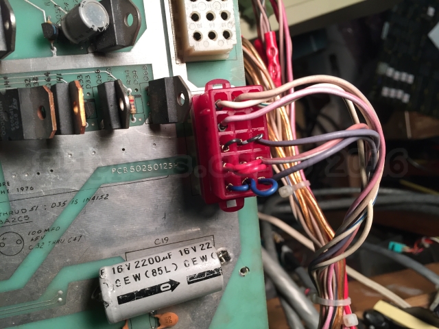
Another problem with these games is the bottom (of three on the side) power connection to the MPU board - usually red. The issue is ALI only used one or at most two pins for the two Grounds and +5VDC supply to the board and if those start to fail then you will have a board that isn't working properly and this may contribute to blown solenoid driver transistors (I need to verify that). The fix is pretty easy - you just jumper the three sets of bottom pins as the photo shows below. I recommend this for ALL ALI MPU System 2. We now provide a kit of the pins and jumper wires. The pins are AMP pins. If the middle row has two wires in place already then don't bother with doing the change to that row. The bottom and next up are the 5VDC common and power and are the critical ones to be upgraded.
We also will shortly have new board connector blocks to replace corroded or otherwise damaged female socket pins as you have to replace the entire base because the individual pins were not designed to be replaced.
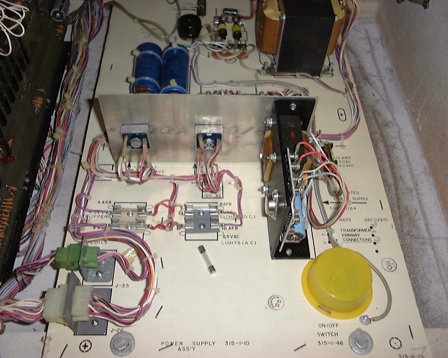
Another common problem with these games are the poor quality fuse holders - I recommend that you change any that are not a hard bakelite or plastic body with a new holder. We sell multi-fuse holders if you can't find them locally. Note the two pair of old fuse holders just to the left of the +5VDC Supply.
And now new fuse holders...

Replacement flat connectors for the bottom card edge connectors are now available - click image below to order pins!

This computer does not use a switch matrix. Each switch is pulled to ground to register on the MPU board. If you have problems with the computer reading switches check the ground return path. You can identify the ground returns as it is the common lead on the switches (jumps from switch to switch). You can then do a continuity test to the logic board Ground trace - the large filter cap on the lower left of the board is a good ground point.
Find the break and fix.
Temporarily you could simply use a jumper wire from the switch ground line to the negative of the main MPU filter capacitor mentioned above to see if that fixes the non-acting switches.
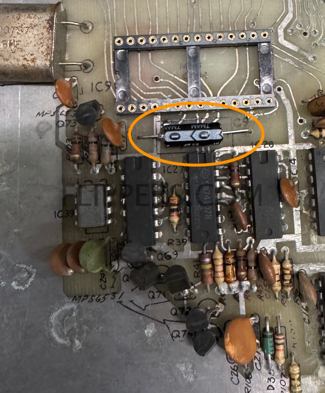
A common problem with older circuit boards are failing electrolytic capacitors - this shows up in ALI boards when capacitor C9 (22/16VDC) fails - leading to erratic booting if the game boots at all.
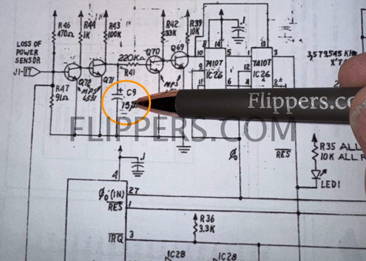
I recommend replacing this capacitor with a similar sized 22mfd @ 10VDC (or higher voltage).
Game board seems to work, passes self tests, but coin switches do not add any credit even though they read correctly in self test.
Make sure you have the jumpers set correctly! Note that the settings in the image are:
GAME ADJUSTMENT
REPLAY
No. OF BALLS - 5
CREDIT ADJUSTMENT
Credit Option - 1
CREDIT PROGRAM (Coin Switch)
Coin Switch 1 - 1 Coin per play (note if set to ZERO no credits!)
Coin Switch 2 - 1 Coin per play (note if set to ZERO no credits!)
Coin Switch 3 - 1 Coin per play (note if set to ZERO no credits!)
MAX CREDITS - 01 (One Credit max - let's make it ten or more!)
REPLAY ADJUSTMENT
(I think you get the idea by now)
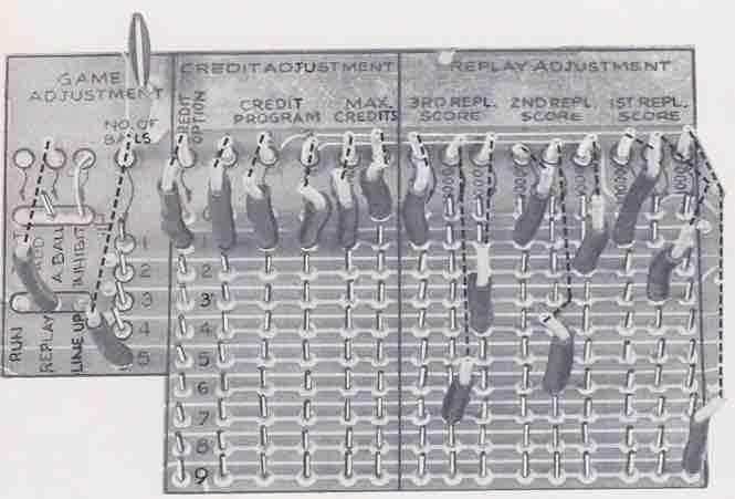
Be sure to have the first jumper on "1", then the next three are the coin switches, followed by two for maximum credits.
We have copies of ALI Operators Manuals including schematics, cabinet wiring diagrams, and troubleshooting for most ALI Solid State pinball games. These include: Boogie, Rock-On, Dy-No-Mite (Dynomite), Getaway, Take Five, Eros, and others - some made by Fascination under license... Here is a sample of one portion of one schematic - this is for Cocktail Pinball AC Power Wiring. You can order the parts and schematics manual from our online store here (later single MPU) or order here for early multiboard games
You can use an ALI 4 player System 2 MPU board in a two player cocktail - the cabinet connector has a built-in jumper to tell the board to be in either two or four player mode.
System 2 MPUs
May 2023 NEWS - we now have a working replacement for the 3 x 6530s in a single sub-board - see below
In both revisions of the MPU the three 6530's are the same three part numbers, however these R6530s (-09(IC5) , -10(IC6), and -11(IC3)) have to be in their correct sockets or the board can not work!. I am again working on replacements for these - have the design worked out, now am going to run off the circuit board to test. Should have results by the summer...note that the Bally Home Model Pinball games did NOT use the 6530 and this will NOT work for them. That will have to be a separate project - unlikely that I will attempt it as the payback is even worse than the time invested in the replacement 6530 RAM/ROM/I-O/Timer project.
The locations for the three 6530s are:
IC3 - R6530-011 or R0007-11
IC5 - R6530-009 or R0008-11
IC6 - R6530-010 or R0006-11
Note that the order of the 6530 IC part numbers is NOT the same order as the socket numbers.
Memory Map:
RAM - 0 - 3Fh (IC-6), 100 - 13Fh (IC-5)
ROM 1400h - 17FFh Fluke 9010 Signature = 776D (IC-5)
ROM 1800h - 1BFFh Fluke 9010 Signature = FE4F (IC-6)
ROM 1C00h - 1FFFh Fluke 9010 Signature = 801E (IC-3)
ROM 1400h - 1FFFh Fluke 9010 Signature = 3271
June 30, 2023 news flash!
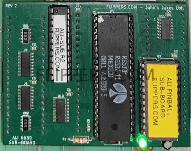
A replacement is now available for the 3 x 6530s - a single simple plug-in sub-board that fits into the three IC sockets for IC3, 5, and 6.
A 6520 is identical to 6820 or 6821 and can be replaced with either, although the 6821 is the more stable upgrade from the 6820.
Technical tips:
Game is dead, no lights at all. Check power cord, power switch, line fuse, get a voltmeter and schematic and see where the line power vanishes...
Game is dead, background lights come on - verify 5VDCpower supply (see above). Then check fuses...
LED #1 - RESET. LED turns on when the game is powered up, then goes off after about 2 seconds. If it does not light or stays lit, then check the 5VDCpower supply first. (note that this LED does not light up clearly on all boards - an easy fix is to replace the 10K resistor directly beside the LED with a 4K7 ohm resistor, or any value from 3K to 5K.)
LED #2 - not used...remove if present, there should be no connection and the associated resistor (R48 - above LED 2) should also be removed. We've seen where if the LED #2 is bad then the first player display only shows ZEROs and nothing else...
LED #3 & #4 - Should light during RESET, then go off/dim and only blink periodically.
Game won't accept coins:
- If the game appears to boot normally then see if the Switch Test is working - see service manual - and check the Coin Switch and the Start Switch for their registering in Switch Test.
- If they don't work then you may have had an electrostatic shock to either the coin switch or the start switch which damages the TTL chips that carry the signal to the 6530s that process the information. You can use the (click -->) DIODE TEST and the schematics to try and find which IC(s) have issues.We sell the schematics here...
Game won't start after creidts added:
- See above (Game won't accept coins:) about switch test.
- If there is a stuck TILT switch (pendulum or ball roll cage) the game will not start. Symptoms include displays working in Attract mode, but after starting the game when the ball rolls over the ball index switch the game immediately goes into TILT (lits up). So make sure the pendulum tilt is in the middle of the metal ring, and that the ball roll Tilt is all the way to the front of the cage!
- The game will ignore ALL switches if a stuck switch is detected during normal game play.
- The game will not start if the "Ball In Play' switch (ball shooter trough) does not make contact at the start of each ball in play.
- Some early MPU (not H) game computers had a "glitch" that would cause the machine to stop working and the lamps to flash. The following is a fix for this situation (only do this IF you have this problem!):
a) IC 28 Pin 13 - Add .001 mfd capacitor to ground. (JR - helps the clock to boot)
b) IC 3 Pin 17 - Lift, bend, or cut the pin so it no longer connects to the IC Socket. (JR - /IRQ is not used on this 6530)
c) IC 29 Pins 1 & 2 - add a 1K ohm resistor to pin 14 (Vcc +5VDC) if not present. (JR - adds a pullup resistor if missing)
Self Test Fails:
1) Remove the ball from the game(shooter trough) otherwise the self test can't always work correctly.
2) The game will not go on from Stuck Switch Test if a switch is stuck closed!
Game starts but one (or more) display doesn't work correctly (verify with 1st press of Self Test button - all displays should count 0 - 9, repeat)):
1)
Reseat MPU board in the three bottom sockets with power off - lift up and push back down a couple of times to clean the wipers.
Game starts but no scoring: make sure runway switch closes otherwise computer ignores all switches. Also if the Outhole Switch doesn't register then the game will start, but not kick the ball into play.
Game ignores some or all switches: If all switches ignored, then look for a jammed closed switch behind a rubber ring or standup target. If you can't spot one, then - using a volt meter with the negative lead tied to common/ground - check if one side of each switch is reading close to 5VDC. If so, then when you trip these switches does the 5VDC on one wire at the switch then go to 0VDC (the other wire is ground)? If not then you have a problem with the switch common (ground) line.
Repairs:
We service the ALI MPUs, (both versions). If you wish for us to take over please wrap the board in anti static bubble wrap, then ship in a sturdy cardboard box according to the following instructions:
If you live outside of Canada you MUST send it to us by Postal Service ONLY! Express Post is inexpensive and has confirmation of delivery and insurance is available. Pretty quick too!
When sending us your circuit board please get a Customs Declaration Form at the Post Office (or when you do this on-line), select the export reason option "OTHER"and write in the space provided "Circuit Board(s) for Repair" to avoid taxes/duties...
Please include a cover letter outlining both the problem and what you would like us to do & your email address, phone number, etc.
Ship to: John's Jukes Ltd. #7 - 3979 Marine Way, Burnaby, BC, Canada V5J 5E3
ALLIED LEISURE PINBALL PARTS CATALOG (April 1976) (5mb) for downloading and ordering parts from us, this covers all the pinball games both regular and cocktail...
Earlier ALI pins included odd-balls like SPOOKSVILLE - called a Shakerball. I have parts, schematics, etc for this game, and here is a service bulletin for that game.
FAQ (Frequently Asked Questions):
> 1) According to John's website it looks like there are 2 sets of ROM part numbers. Are these interchangeable with the other set? (i.e. if I have a set of -009 -010 and -011, and another set of -006, -007, and -008, can I use a -006 in place of -010 or do the numbered sets need to stay together?)
>
Yes, you can intermix them - just make sure the correct part number is in the IC socket.
> 2) If I only hook +5V to the board outside of the game and assuming everything on the board works, should it boot or does it need to be connected to something else in the cabinet to actually boot? (I'd be looking for LED1 to light, then go out after about 2 seconds) If I make/use a 5V test fixture (of sorts), what amperage power supply would be acceptable for a test like this?
>
Yes, the board will boot with just good 5VDC, and the LEDs should co-operate.
> 3) AC Ripple test: I just want to make sure I'm doing/checking this right. I hook + on my DMM to +5VDC on the power supply itself and - on the DMM to ground/common on the power supply itself. I set the DMM to VDC and confirm +5VDC. I then switch to VAC and look for no fluctuation. Should I also do this on C19 on the board too or is just testing at the power supply sufficient?
Testing at the power supply should be sufficient, if you are using a switching supply then it is very unlikely there would be any ripple at all.
>
> 4) Is there a good way to test the 6520s? I have a Williams Flash which (as far as I know) I should be able to swap into the driver board to test to see if they work. Or is there a better/different way (ie testing pins for shorts or something like that?
>
the 6520s can be replaced with 6820/6821s, they function identically.
> 5) Assuming the reset circuit on all 3 boards is bad, what section of the board should I be looking at to test (I love how Atari outlines this stuff, it makes it super easy to troubleshoot)? Sorry, I know this is sort of a vague question.
>
Check if the Reset signal is getting to the CPU - Reset goes Low briefly (1/2 second perhaps) on PowerUp and then should go High. Low is defined as under 1VDC and High is over 2.5VDC. If so, then the CPU is the next suspect. Of course you need a good Clock signal too.
A logic probe is a lot of help in doing basic tests, it shows if the clock is toggling, and if you have activity on the Address and Data buses...
TESTING YOUR ALI GAME
1. TEST MODE ONE (Credit & Score LED's)
To initiate this test, remove the ball from the Out-Hole, raise/lift all Drop Targets, then press the Self-Diagnostic switch usually found on the Coin Door. Both SCORE and CREDIT displays should sequence from 0 through 9, then repeat. The first digit on the right side of all SCORE displays will always be zero.
2. TEST MODE TWO (Stuck Switch & Switch Verification Test) Press CREDIT button for 5 seconds, then observe:
(1) Game credit display shows "02".
(2) Left side score display will show the number of switch that is closed.
Then momentarily press each switch to verify recognition by the computer. The switch number will be displayed on Score Display #1. The game will not progress to the next test mode if the SCORE display shows that any switch is stuck in the closed position.
3. TEST MODE THREE (Vibration Test)
Press the test switch for 2 seconds. The game credit display should then show "03".
Tap very lightly the surface of the Playfield. If there are any switches not adjusted correctly (gap too close), the number of such switch will be displayed and latched in Score Unit #1. Make the necessary switch adjustments. To unlatch the number from the score display, press the GAME START button.
4. TEST MODE FOUR (Lamps Test "A")
Press the test switch for 2 seconds. The CREDIT display will show "04". Ignore any numbers on the SCORE display. The D. C. flasher lamps will remain lit through this test. The following lamps also should be lit:
(a) EXTRA BALL WHEN LIT .
(b) Alley Value 1, 2, 3 and 4.
(c) Star Value #1.
(d) SPECIAL WHEN LIT.
(e) EXTRA BALL WHEN LIT
Ignore the GAME OVER lamp.
5. TEST MODE FIVE (Lamps Test "B")
Press the GAME START button for 2 seconds. The CREDIT display will show "05". Then observe that these lamps are lit:
(a) S-T-A-R value 1, 2, 3 and 4.
(b) 10,000 BONUS lamp, DOUBLE BONUS lamp and TRIPLE BONUS lamp.
The D. C. flasher lamps, are out during this test.
6. TEST MODE SIX (D. C. Flasher Lamps)
Press the CREDIT button for 2 seconds. The CREDIT display will show "06". SAME PLAYER SHOOTS AGAIN lamp will be lit. The D. C. flasher lamps come on at this time.
7. TEST MODE SEVEN (Score Displays)
Press the CREDIT button for 2 seconds. The CREDIT display will show "07" and all score displays go dark.
8. TEST MODE EIGHT (Lamps Test "C")
Press the CREDIT button for 2 seconds. The CREDIT display will show "08" ... then observe:
(a) The BONUS lamps count down from 9,000 to 1,000. (The 10,000 lamp was tested in MODE FIVE.)
(b) The GAME OVER lamp flashes after the 1,000 BONUS lamp.
NOTE: There are two GAME OVER lamps: one on the Shadow Box, and the other on the Playfield below the two Bull's-Eye Targets. This one serves as an attraction feature only.
9. TEST MODE NINE (Coils and Sound Test)
Press the CREDIT button for 5 seconds. The CREDIT display will show "09''. Ignore the score displays during this test. The coils (solenoids) should energize in the following sequence:
(a) Bottom left Thumper Bumper and Drop Targets 1 and 5. (b) Rebound Kicker. and Drop Targets 2 and 8.
(c) Drop Targets 3 and 6.
(d) Drop Targets 4 and 7.
(e) Left Thumper Bumper.
(f) Right Thumper Bumper.
(g) Out-Hole Kicker.
(h) 1,000-point sound (low tone). (i) 100-point sound (middle tone). (j) 10-point sound (high tone).
(k) Replay Knocker.
(1) Free Ball (Flag) Gate and GATE OPEN WHEN LIT lamp lights.
(The Flipper buttons must be held IN for Flipper coils to energize immediately after Replay Knocker.)
10. TEST MODE TEN (Combination Test)
This test can be used as a method of testing a newly installed Logic Board.
Press the CREDIT button for 10 seconds. The CREDIT display should show "Oc". Enjoy the show!
TEST MODE NOTES
1. You MUST remove ball from outhole before starting TEST MODE.
2. When in the "stuck switch" test, all switches MUST BE OPEN or game will not proceed to next test mode,
3. Machine is programmed to ignore ALL switches if a stuck closed switch is detected during game play. The EXCEPTION is if a coil drive switch is stuck closed; the computer will ignore that switch and continue game play. If another coil drive switch is stuck closed, the 1st stuck switch will be reactivated and the 2nd switch will be ignored.
4. Game will not score if ball in play switch (ball shooter trough) does not make contact at start of each ball in play.
SERVICE BULLETINS:
HARDWARE REVISIONS
Some games had a "glitch" that would cause the machine to stop working and the lamps to flash. The following is a fix for this condition:
IC 28 Pin 13 - Add .001 mfd capacitor to ground.
IC 4 Pin 17 - Lift or cut pin off so it no longer connects.
IC 29 Pins 1 + 14 - add 1K ohm resistor to ground.
THUNDERBOLT uprights - early versions
Holding credit button in while ball was in "collect hole" causes game to lock up.
Re-wire "Collect Right Value" and "Collect Left Value" switches to bulls-eye targets instead of outhole kickers.
(jrr-at-flippers-dot-com for those who do not have their browser set to open their email client) |
